Common Description
Consisting of a pressure balanced gear pump, DC motor, multi-functional manifold, valves, tank, ect., this energy unit is made to operate material dealing with tools. The lowering movement is achived by the solenoid valve together with the lowering velocity managed by an adjustable needle valve. The left and correct functions are outfitted having a dual pilot operated test valve and cross-over relief valves.
Remark: Please consult our product sales engineer for your various pump displacement, motor power or tank capability.
Particular Notes
one. This power unit is of S3 duty cycle, i.e.,non-continuous operation,thirty seconds on and 270 seconds off.
two. Clean the many hydraulic components concerned before installation of the electrical power unit.
three. Viscosity of the hydraulic oil shoud be 15~46 cst, which ought to also be clean and free of impurities.N46 hydraulic oil is encouraged.
four. This energy unit really should be mounted horizontal.
5. Check the oil degree from the tank right 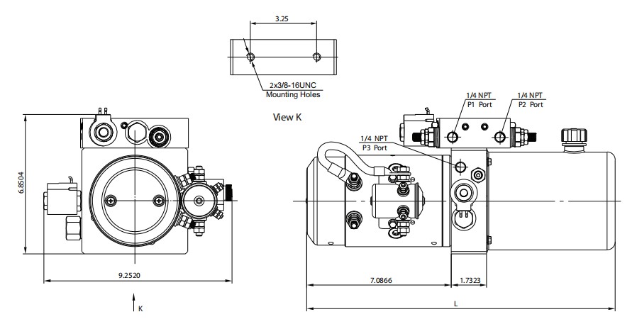 after the initial start off on the energy unit.
6. Oil altering is required just after the initial 100 operation hours, afterwards when every single 3000 hours.
DUMP TRAILER Electrical power UNIT- SINGLE ACTING
Basic Description
This power unit features a power up gravity down circuit. Begin the motor to lengthen the cylinder and activate the solenoid valve to retract the circuit. Guide override to solenoid valve might be provided if required. Also a pressure compen sated flow control is often extra to your circuit to regulate the descent velocity on the cylinder.
Remark: Please talk to our sales engineer for the distinctive pump displacement, motor energy or tank capability.
Specific Notes
1. This power unit is of S3 duty cycle, i.e., non-continuous operation, thirty seconds on and 270 seconds off.
2. Clean all the hydraulic parts concerned prior to installation of the power unit.
3. Viscosity of your hydraulic oil shoud be 15~46 cst,which need to also be clean and free of impurities.N46 hydraulic oil is advisable.
four. The power unit really should be mounted horizontally.
5. Check the oil degree during the tank right after the initial running of your power unit.
6. Oil shifting is required soon after the first one hundred operation hrs, afterwards the moment every 3000 hrs.
DUMP TRAILER Electrical power UNIT-DOUBLE ACTING
Common Description
This electrical power unit features a electrical power up energy down circuit with load holding on both A & B ports. A strain compensatred movement control is usually added to circuit to regulate the decent velocity of your cylinder.
Distinctive Notes
1. This energy unit is of S3 duty cycle, i.e., non-continuous operation, thirty seconds on and 270 seconds off.
2. Clean all the hydraulic parts concerned in advance of installation  of the energy unit.
3. Viscosity with the hydraulic oil shoud be 15~46 cst, which really should also be clean and absolutely free of impurities. N46 hydraulic oil is encouraged.
four. The energy unit must be mounted horizontally.
five. Check the oil level while in the tank soon after the original working with the energy unit.
6. Oil shifting is required following the original one hundred operation hours, afterwards the moment every single 3000 hrs.
Common Description
Outfitted with the zero leak bidirectional checking sole-noid valves, this electrical power unit is intended for your operation of two independent circuits. Which are respectively for your key and subordinate platforms from the double scissors lift. Two cut-off valves are employed for reducing the machine manually in situation of power reduction. If more independent circuits are required for the application please speak to us for availability.
Remark: one. Please seek advice from our income engineer for your distinctive pump displacement, motor power or tank capability.
2. CSA or UL certified motors are 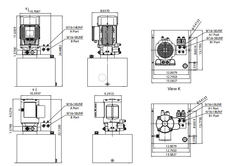 available on request.
Particular Notes
one. The AC motor is of S3 duty cycle, which might only get the job done intermittently and repeatedly, i.e., 1minute on and 9 minutes off.
two. Clean every one of the hydraulic parts concerned prior to set up of the electrical power unit.
three. Viscosity of your oil shoud be 15~46 cst,as well as the oil ought to be clean and no cost of impurities,N46 hydraulic oil is proposed.
four. The electrical power unit should be mounted vertically.
5. Check the oil degree while in the tank soon after the first operating on the power unit.
6. Oil modifying is needed right after the preliminary a hundred operation hrs,afterwards when each 3000 hrs.
Introduction
A mindful assessment on the ailments surrounding a conveyor is necessary for accurate conveyor chain variety. This part discusses the fundamental considerations demanded for effective conveyor chain choice. Roller Chains are sometimes employed for light to reasonable duty materials dealing with applications. Environmental conditions may possibly call for using special materials, platings coatings, lubricants or the means to operate without having extra external lubrication.
Basic Details Expected For Chain Assortment
? Type of chain conveyor (unit or bulk) which includes the method of conveyance (attachments, buckets, via rods and so forth).
? Conveyor layout which include sprocket places, inclines (if any) and also the amount of chain strands (N) to become employed.
? Amount of materials (M in lbs/ft or kN/m) and sort of materials to be conveyed.
? Estimated weight of conveyor components (W in lbs/ft or kN/m) such as chain, slats or attachments (if any).
? Linear chain pace (S in ft/min or m/min).
? Environment through which the chain will operate together with temperature, corrosion circumstance, lubrication issue and so forth.
Phase 1: Estimate Chain Tension
Use the formula below to estimate the conveyor Pull (Pest) and after that the chain stress (Check). Pest = (M + W) x f x SF and
Test = Pest / N
f = Coefficient of Friction
SF = Velocity Factor
Stage two: Make a Tentative Chain Choice
Utilizing the Check value, produce a tentative variety by selecting a chain
whose rated operating load higher than the calculated Check value.These values are proper for conveyor support and are diff erent from people shown in tables at the front in the catalog which are associated with slow speed drive chain usage.
Moreover to suffi cient load carrying capacity generally these chains needs to be of a specific pitch to accommodate a preferred attachment spacing. By way of example if slats are to be bolted to an attachment just about every one.five inches, the pitch from the chain chosen ought to divide into one.5?¡À. As a result 1 could use a 40 chain (1/2?¡À pitch) with the attachments every 3rd, a 60 chain (3/4?¡À pitch) using the attachments just about every 2nd, a 120 chain (1-1/2?¡À pitch) with the attachments each pitch or even a C2060H chain (1-1/2?¡À pitch) with the attachments every pitch.
Stage 3: Finalize Selection – Calculate Real Conveyor Pull
After generating a tentative variety we need to verify it by calculating
the actual chain tension (T). To do this we need to fi rst determine the actual conveyor pull (P). From the layouts shown on the appropriate side of this webpage pick out the proper formula and determine the total conveyor pull. Note that some conveyors may very well be a combination of horizontal, inclined and vertical . . . in that case calculate the conveyor Pull at every section and add them with each other.
Phase four: Determine Greatest Chain Stress
The utmost Chain Tension (T) equals the Conveyor Pull (P) as calculated in Step three divided through the amount of strands carrying the load (N), occasions the Speed Issue (SF) proven in Table two, the Multi-Strand Issue (MSF) shown in Table 3 as well as Temperature Element (TF) shown in Table four.
T = (P / N) x MSF x SF x TF
Stage five: Verify the ?¡ãRated Working Load?¡À from the Picked Chain
The ?¡ãRated Operating Load?¡À of the chosen chain must be higher than the Greatest Chain Tension (T) calculated in Step four over. These values are proper for conveyor 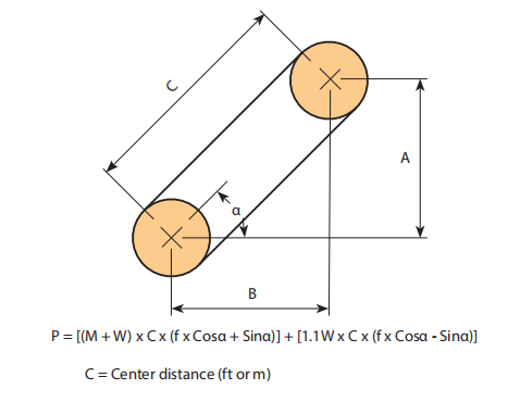 support and therefore are diff erent from these proven in tables with the front on the catalog that are related to slow speed drive chain utilization.
Step 6: Examine the ?¡ãAllowable Roller Load?¡À from the Chosen Chain
For chains that roll around the chain rollers or on leading roller attachments it can be required to examine the Allowable Roller Load?¡À.
Note: the Roller load is determined by:
Roller Load = Wr / Nr
Wr = The complete bodyweight carried by the rollers
Nr = The amount of rollers supporting the weight.
Leaf Chains are made for high load, slow pace stress linkage applications. Generally these are specifi ed for reciprocating movement lifting gadgets such as fork lifts or cranes. These chains are generally supplied to a specifi c length and are connected to a clevis block at every single finish. The clevis may perhaps accommodate male ends (within or occasionally referred to as “articulating” hyperlinks) or female ends (outside or even the backlinks on the pin website link) as expected (see illustration below)
Leaf chains can be found in 3 series; AL (light duty), BL (hefty duty), or LL (European normal). For new selections we endorse the BL series in preference to the AL series as the latter has become discontinued as a acknowledged ASME/ANSI regular series chain. BL series chains are developed in accordance with the ASME/ANSI B29.eight  American Leaf Chain Conventional. LL series chains are developed in accordance with the ISO 606 global leaf chain regular.
A chain with an even amount of pitches always has a one male and 1 female finish. It is actually more common to have the chain possess an odd amount of pitches during which case the both ends are going to be either male (most common) or female (much less com-mon). When ordering lengths with an odd quantity of pitches male ends are provided except if otherwise mentioned. Clevis pins, ordinarily with cotters at just about every finish, are applied to connect male chain ends to female clevis blocks. Chains with female ends are sometimes (but not usually) linked on the clevis block with a cottered style connecting website link. The connecting website link will be the female finish element in this case.
Leaf Chain Assortment
Utilize the following formula to verify the variety of leaf chain:
Minimal Ultimate Strength > T x DF x SF
T: Calculated Greatest Chain Stress
DF: Duty Issue
SF: Support Aspect
Note that the highest allowable chain speed for leaf chains is 100ft per minute.
Standard Info
We offer one of many most extensive lines of specialty Servicing Absolutely free roller chain merchandise offered to fi t a broad array of particular application requirements. Designers can pick the series that best fi ts the distinct requirements on the application. These chains really should be specifi ed only when conditions prohibit the usage of lubricating oil since, on the whole, a well lubricated conventional chain will off er longer daily life in contrast which has a servicing cost-free chain. In some applications having said that lubrication isn?¡¥t possible and so using a self lubricated or sealed roller chain is important.
Common Properties of Maintenance Absolutely free Roller Chain Products
Sintered Bushed (SL-Series) Chains
Oil impregnated powdered metal sintered bushings release oil for the chain joint as a result of friction created involving the pin and bushing because the chain articulates more than the sprocket teeth. These chains are rollerless and so use thick sectioned powdered metal bushings which could hold a large volume of oil.
PT Variety Roller Chains
Oil impregnated powdered metal sintered bushings release oil to your chain joint as a result of friction created involving the pin and bushing as the chain articulates more than the sprocket teeth. These chains possess rollers to smooth the action more than sprocket teeth. Roller hyperlink plates are a single dimension thicker to increase strength. Side plates and pins have particular coatings to stop rust. 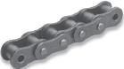 C-Type Roller Chains
Identical as above except that the side plates are all typical thickness. The strength on the CS Sort chains is less than the PT Form but better than the SL style. Attachments with standard dimen-sions may be used for this series and as a result these are usually utilised on modest materials managing conveyors.
P-Ring Chains
Specifi ed on smaller pitch roller chains O-Ring chains employ a rubber seal to help keep lubricating grease in even though stopping the penetration of dirt and various contaminants to the pin/bush-ing bearing region.
Seal Guard Roller Chains
Specifi ed on more substantial pitch roller chains Seal Guard chains employ a stainless steel seal to keep lubricating grease in although avoiding the penetration of dirt together with other contaminants in to the pin/bushing bearing area.
Sort 304 Stainless
All parts are created from AISI Variety 304 (18-8) austenitic stainless steel. This materials off ers very good chemical and temperature resistance within a broad choice of diverse applications. Due to the fact Form 304 stainless steel can not be heat treated the mechanical power and wear performance is inferior to typical carbon steel chains.
Sort 316 Stainless
All elements are produced from AISI Variety 316 Molybdenum-bearing stainless steel. The molybdenum gives the alloy greater all round 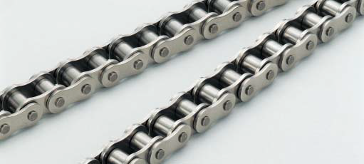 corrosion resistance in contrast with Style 304 stainless steel notably greater resistance to pitting and strain corrosion cracking within the presence of chlorides. Mechanical strength and wear overall performance are equivalent to Style 304 stainless steel chain.
600 Series Stainless
Pins, bushings and rollers are made from 17-4PH stainless steels which can be age hardened for improved resistance to put on elongation. The corrosion resistance of this series is equivalent (though slightly inferior) to Form 304 stainless steel. The operating temperature selection of this material nevertheless can be not as wide as Type 304 stainless steel.
Mega Chain:
All elements are made from AISI Variety 304 (18-8) austenitic stainless steel. Readily available in two versions (Mega Chain and Mega Chain II) which use diff erent bodily confi gurations to get added power that may be similar to that of carbon steel chains. The working loads of those chains are superior to that of normal 304 stainless steel chains resulting from a higher pin/bushing bearing locations. On top of that the two versions possess a distinctive labyrinth style seal style and design that helps prevent the penetration of abrasive foreign elements to the inner sporting components.
Standard Information and facts
We off er several different corrosion and/or temperature resistant roller chain solutions to suit the particular demands of practically any application. These vary from plated or coated carbon steels to several diff erent stainless steel sorts that could be picked based mostly on the sought 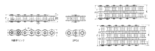 after mixture of put on resistance, strength, corrosion resistance and resistance to extremes in operating temperatures.
Nickel Plating
Ideal for mild corrosive disorders such as outside support. Frequently used for decorative functions. Chain components are plated before assembly for uniform coverage of inner components.
Kind 304 Stainless
Our normal stainless steel product off ers outstanding resistance to corrosion and operates efficiently more than a broad selection of temperatures. This materials is slightly magnetic as a result of function hardening of your elements during the manufacturing processes.
Kind 316 Stainless
This material possess greater corrosion and temperature resistance in contrast with Style 304SS. It is frequently used in the meals processing field as a consequence of its resistance to anxiety corrosion cracking inside the presence of chlorides such as are discovered in liquid smoke. The magnetic permeability of this materials is particularly minimal and is often considered nonmagnetic however it is not viewed as to get prspark oof.
600 Series Stainless
Pins, bushings and rollers are made from 17-4PH stainless steels which may be hardened for enhanced resistance to dress in elongation. The corrosion resistance of this chain is similar to
Type 304SS. The operating temperature choice of this material having said that is just not as wonderful as Type 304SS.
Mega Chain:
A substantial strength 304 stainless steel chain. Available in two versions which use diff erent mechanical confi gurations to acquire extra strength. Both versions off er higher doing work loads as a consequence of a higher pin/bushing bearing location and also a distinctive labyrinth form seal that helps protect against the penetration of abrasive foreign materials towards the internal wearing parts.
Double Pitch roller chains are made in accordance with all the ASME/ANSI B29.three (Transmission Series) and B29.four (Conveyor Series) American roller chain specifications. Generally these chains are related to ASME/ANSI standard items except the pitch is double. ![]() These are obtainable in Transmission Series, Conveyor Series with Standard (little) Rollers and Conveyor Series with Big (oversized) Rollers.
These are obtainable in Transmission Series, Conveyor Series with Standard (little) Rollers and Conveyor Series with Big (oversized) Rollers.
Transmission Series
This series is often employed on drives with slow to moderate speeds, very low chain loads and long center distances. Side plates possess a fi gure ?¡ã8?¡À contour. The chain variety is obtained by incorporating 2000 to the ASME/ANSI chain quantity and also the prefi x letter ?¡ãA?¡À. Note that some companies tend not to use a prefi x letter for this series so the chains may perhaps be represented as A2040, A2050 and so forth. or 2040, 2050 and so on.
Conveyor Series with Standard (little) Rollers
This series is usually used on light to moderate load material managing conveyors with or without attachment hyperlinks. The side plate contour is straight for improved sliding properties. Pitch sizes of 1-1/2?¡À and more substantial have ?¡ãHeavy?¡À series hyperlink plates (i.e. website link plates with the subsequent more substantial chain size. The chain number is found by including 2000 to the ASME/ANSI chain quantity and also the prefi x letter ?¡ãC?¡À. Chains with all the ?¡ãheavy?¡À sort side plates use a suffi x letter ?¡ãH?¡À.
Conveyor Series with Significant (oversized) Rollers
These chains possess huge rollers to ensure the chain rolls on the conveyor track lowering friction. Chain numbers are observed in the identical way as mentioned over except the last digit on the chain amount is modified from ?¡ã0?¡À to ?¡ã2?¡À which denotes the huge roller.
Sprockets
On the whole sprockets need to be produced specially for these chains in accordance for the ASME/ANSI B29.three and B29.four requirements on the other hand, for Transmission Series and Conveyor Series with Standard (little) Rollers, ASME/ANSI B29.1 Conventional roller chain sprockets might be utilized offered the amount of teeth is thirty or a lot more.
The following actions should be applied to select chain and sprocket sizes, ascertain the minimum center distance, and calculate the length of chain desired in pitches. We will generally use Imperial units (such as horsepower) within this segment nevertheless Kilowatt Capacity tables can be found for each chain dimension inside the preceding part. The assortment process is the same regardless with the units made use of.
Step 1: Determine the Class with the Driven Load
Estimate which of your following greatest characterizes the affliction of the drive.
Uniform: Smooth operation. Little or no shock loading. Soft start out up. Moderate: Standard or reasonable shock loading.
Hefty: Extreme shock loading. Frequent starts and stops.
Stage two: Figure out the Service Element
From Table one beneath decide the ideal Service Factor (SF) for that drive.
Stage 3: Determine Design and style Energy Necessity
Style and design Horsepower (DHP) = HP x SF (Imperial Units)
or
Style Kilowatt Energy (DKW) = KW x SF (Metric Units)
The Design and style Power Necessity is equal to the motor (or engine) output power occasions the Service Element obtained from Table 1.
Stage four: Create a Tentative Chain Variety
Create a tentative variety of the expected chain size while in the following manner:
one. If applying Kilowatt 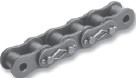 power – fi rst convert to horsepower for this stage by multiplying the motor Kilowatt rating by one.340 . . . This is vital since the swift selector chart is shown in horsepower.
2. Locate the Design Horsepower calculated in phase 3 by reading up the single, double, triple or quad chain columns. Draw a horizontal line via this value.
three. Locate the rpm of your compact sprocket over the horizontal axis of your chart. Draw a vertical line by means of this worth.
four. The intersection from the two lines need to indicate the tentative chain variety.
Phase five: Decide on the quantity of Teeth for your Modest Sprocket
When a tentative selection of the chain dimension is manufactured we need to ascertain the minimal number of teeth required to the compact sprocket necessary to transmit the Design and style Horsepower (DHP) or even the Design Kilowatt Energy (DKW).
Phase 6: Identify the amount of Teeth to the Big Sprocket
Utilize the following to determine the quantity of teeth for the significant sprocket:
N = (r / R) x n
The number of teeth over the big sprocket equals the rpm from the little sprocket (r) divided from the sought after rpm of the big sprocket (R) times the amount of teeth over the smaller sprocket. When the sprocket is as well significant for the area offered then several strand chains of a smaller sized pitch should really be checked.
Phase 7: Ascertain the Minimal Shaft Center Distance
Use the following to calculate the minimal shaft center distance (in chain pitches):
C (min) = (2N + n) / six
The above is usually a guidebook only.
Phase 8: Test the Last Choice
In addition bear in mind of any possible interference or other space limitations that could exist and adjust the choice accordingly. In general the most efficient/cost eff ective drive employs single strand chains. This is certainly simply because several strand sprockets are additional costly and as might be ascertained by the multi-strand components the chains become less effi cient in transmitting power since the amount of strands increases. It’s therefore normally very best to specify single strand chains every time attainable
Stage 9: Ascertain the Length of Chain in Pitches
Use the following to calculate the length on the chain (L) in pitches:
L = ((N + n) / two) + (2C) + (K / C)
Values for “K” can be discovered in Table four on web page 43. Recall that
C will be the shaft center distance offered in pitches of chain (not inches or millimeters and so forth). Should the shaft center distance is acknowledged inside a unit of length the value C is obtained by dividing the chain pitch (within the exact same unit) from the shaft centers.
C = Shaft Centers (inches) / Chain Pitch (inches)
or
C = Shaft Centers (millimeters) / Chain Pitch (millimeters)
Note that whenever probable it is ideal to utilize an even amount of pitches to be able to steer clear of the use of an off set link. Off sets tend not to possess the same load carrying capability because the base chain and must be avoided if attainable.
? Type of input energy (electrical motor, internal combustion engine with mechanical or hydraulic drive).
? Type of products to become driven.
? Amount of horsepower required to provide suffi cient power towards the driven shaft.
? Full load pace in the quickest working shaft (rpm).
? Desired speed in the slow operating shaft ( or even the required velocity ratio). NOTE: If speeds are variable decide the horsepower for being transmitted at each speed.
? Diameters on the drive and driven shafts . . . This worth may possibly restrict the minimum number of teeth for the sprockets.
? Center distance of the shafts.
? Note the position and any room limitations that may exist. Generally these limitations are within the maximum diameter of sprockets (this restricts using single strand chains) or the width of the chain (this restricts the use of multi-strand chains).
? Conditions of your drive which includes a determination of the class of load (uniform, reasonable or hefty), severe operating temperatures or chemically aggressive environments needs to be noted.
Abbreviations Used in Equations
N Quantity of teeth about the big sprocket.
n Number of teeth over the compact sprocket.
R Pace in revolutions per minute (rpm) on the significant sprocket.
r Pace in revolutions per minute (rpm) with the tiny sprocket.
C Shaft center distance in chain pitches.
HP Horsepower rating of your drive motor or engine.
KW Kilowatt power rating of drive motor or engine if making use of metric units.
SF Service Factor
Roller chains are one particular with the most efficient and value eff ective methods to transmit mechanical electrical power in between shafts. They operate more than a wide array of speeds, take care of large working loads, have extremely tiny vitality losses and therefore are usually low-cost in contrast with other methods
of transmitting energy. Profitable choice involves following quite a few rather very simple steps involving algebraic calculation plus the utilization of horsepower and service aspect tables.
For almost any provided set of drive conditions, there are a variety of probable chain/sprocket confi gurations which will successfully operate. The designer hence needs to be conscious of several essential selection principles that when utilized correctly, aid balance overall drive functionality and value. By following the actions outlined within this area designers ought to be capable to create choices that meet the requirements from the drive and are value eff ective.
Standard Roller Chain Drive Principles
? The recommended variety of 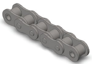 teeth for your tiny sprocket is 15. The minimal is 9 teeth – smoother operation is obtained with far more teeth.
? The encouraged maximum number of teeth to the massive sprocket is 120. Note that when much more teeth lets for smoother operation possessing also numerous teeth leads to chain jumping off the sprocket immediately after a rather smaller quantity of chain elongation because of wear – That’s chains using a very significant number of teeth accommodate much less wear in advance of the chain will no longer wrap about them correctly.
? Speed ratios ought to be 7:one or less (optimum) rather than higher
than 10:1. For greater ratios the usage of numerous chain reductions is recommended.
? The encouraged minimum wrap from the small sprocket is 120°.
? The encouraged center distance among shafts is 30-50 pitches of chain. You will discover two exceptions to this as follows:
1. The center distance should be better than the sum of your outside diameters on the driver and driven sprockets to stop interference.
2. For speed ratios higher than 3:one the center distance should not be significantly less compared to the outdoors diameter of the large sprocket minus the outside diameter with the compact sprocket to assure a minimum 120° wrap about the small sprocket.
Any harm within the teeth surfaces of a sprocket diminishes the existence in the conveyor chain.
With standard sprockets, significantly worn sprocket teeth have been repaired by teeth padding or the whole sprocket was replaced. In either situation, restore was expensive and with teeth padding, accuracy was impaired. We developed new sprockets with detachable teeth for independent replacement. This sprocket is highly rated by our consumers for the dramatic savings in expense and time.
Construction
The teeth could be 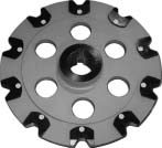 replaced by two techniques: person tooth substitute or sectional teeth replacement.
The bolts and nuts employed for mounting the teeth on to your sprocket are spot-welded to prevent loosening.
The respective structures are illustrated over the right.
The above photograph as well as major right illustration display a sprocket for individual tooth substitute. Since the joint face concerning the replaced teeth and also the sprocket is formed in a one of a kind arc, the bonding accuracy is large plus the sprocket power is enhanced. Additionally, because the load acting within the mounting bolts is decreased, there’s much less possibility of loosening. This sprocket construction is patented.
You will find two sorts of hubs: cast steel and welded sheet steel hubs. Cast steel hubs are utilised for substantial sprockets obtaining heavy loads and welded sheet steel hubs for other applications.
For Use at Low-temperature
When making use of conveyor chains at low-temperature this kind of as in the refrigerator or in the cold environment, the next problems may possibly arise.
1) Reduced temperature brittleness
Normally, a material is embrittled at low-temperature and shock resistance is lowered. This phenomenon is known as low-temperature brittleness, and also the degree of embrittlement differs from materials to materials.
The support restrict of a conveyor chain depends upon its specifications.
two)Influence of freezing
At low-temperature, bending failure, roller rotation failure, fixing of chain, and so on. may very well be triggered from the freezing of penetrated water or deposited frost during the clearance involving pins and bushings, bushings and rollers or inner plates and outer plates. These situations bring about an overload to act around the chain and drive, diminishing the life with the chain.
To avoid freezing, in general, it truly is recommended to fill the clearances by using a low-temperature lubricant suitable for the support temperature to stop water, frost, and so forth. from penetrating  the respective portions on the chain. For lubrication, a silicon based mostly grease is advisable.
For Use at High-temperature
Chains strength is diminished by high-temperature ambiance, direct conveying of high-temperature loads, or radiated heat, and so forth. The service restrict at high-temperature depends not around the temperature on the support natural environment however the temperature and material on the chain physique.
Following conditions may arise when chains are made use of at high-temperature:
1) High temperature brittleness and fracture by lowered hardness of heat handled material
two) Brittleness induced by carbide precipitation
three) Abnormal dress in by scale
four) Fatigue fracture triggered by repeated thermal shock (cooling and growth)
five) Abnormal wear on account of a rise during the coefficient of friction
six) Creep fracture
seven) Fracture on account of thermal fatigue of welded area
eight) Effects brought on by thermal expansion
?Stiff back links and rotation failure on account of decreased clearance ?Fatigue fracture as a consequence of lowered fitting force
9)Lubrication failure and stiff back links on account of deterioration and carbonization of lubricating oil
Grease fantastic in heat resistance include people based upon silicon, graphite or molybdenum disulfide.
For use at high-temperature, high-temperature resistance bearings and stainless steel bearings are advisable.
In general, a chain is bent in transverse direction only. However, a 3D Bending Conveyor Chain is often structurally bent not merely horizontally but in addition vertically. It really is made use of to get a conveyor line which moves vertically and improvements in direction.
X Type Chains for Trolleys, and Electrical power & Free Conveyors
X-type Chains are employed for trolleys, and electrical power & free conveyors. They are drop-forged rivetless chains featuring high strength, lightweight and easy removal of components. The bottom left photo shows an X-type Chain utilised as a trolley conveyor with only one rail.
The bottom right photo shows an X-type Chain utilized for a electrical power & free conveyor. An additional rail is installed to receive the load for higher transfer capability.
A energy & free conveyor generally has a so-called stop and go function to  connect and disconnect conveyed materials with and from the chain, so that the conveyed materials can be temporarily stopped, mixed and stored.
Three kinds of X-type Chains are available according to required strength.
Z-type Chain for Light Load Trolley Conveyors
A Z-type Chain for trolley conveyors is made use of for service similar to that of X-type Chains described on the previous page, but is suitable for light loads. It’s widely employed in conveyors supplying parts, and devices for storing and unloading parts on automobile assembling lines.
Z-type Chain for Light Load Trolley Conveyors
A Z-type Chain for trolley conveyors is used for service similar to that of X-type Chains described on the previous page, but is suitable for light loads. It is widely made use of in conveyors supplying parts, and devices for storing and unloading parts on automobile assembling lines.
FH Variety Chain for Freeyor
An FH Type Chain is utilised for the same purpose as an X-type Chain and Z-type Chain. While X-type Chain is designed for heavy loads and Z-type Chain is for light loads, FH Form Chain is used for intermediate loads. While X-type Chain and Z-type Chain is often vertically bent only slightly, FH-type Chain can be bent both vertically and horizontally, which makes it suitable for any conveyor line moving vertically. We manufacture three kinds of FH-type Chains different in pitch.
Towline Low-Selec-Tow Chain
A towline conveyor has a mechanism to convey dollies caught by a chain buried in the floor. Our chain for towline conveyor is called LST chain (Low-selec-tow chain).
LST Chain is usually bent horizontally and can also move on a slight incline. It really is made by forging, and a recess for hooking a dog is formed at the center of each link.
BF Type Bushing Chain for Water Remedy Drive Unit
This chain is applied to connect water therapy equipment to a electrical power source. Inside the previous, JIS/ ANSI kind roller chains had been employed. For enhanced corrosion resistance, each of the parts are now created of 13Cr stainless steel. Because the chain is operated at a slow pace, a bushing chain without the need of rollers is made use of. The sprockets are interchangeable with JIS/ ANSI roller chain sprockets.
We manufacture seven forms of BF Kind Bushing Chains inside a range from 120 to 240, which includes heavy-duty sort.
Chains applied for collecting accumulated sediment in setting basins and sedimentation basins or removing the collected sediment in sewage treatment services and also other water therapy facilities need in particular high resistance to corrosion and put on given that they are right exposed to sewage 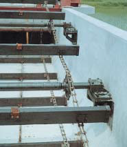 and sludge. A filth getting rid of chain is moved at a rather fast velocity on an practically vertically put in rail, although the operation frequency is minimal, so WS Variety Roller Chain is made use of. Conversely, a chain for raking up and/or out filth is driven at an exceptionally slow velocity and doesn’t demand rollers, so WAS Sort Bush Chain is used.
Eighteen varieties of WS Style and six forms of WAS Style Chain are available.
(a) WS Sort Roller Chain
A WS Form Roller Chain is designed to supply large corrosion resistance and wear resistance for lengthy services during the extreme natural environment of water remedy applications.
Because the operating time of this type of products is comparatively short, pins and bushings of hardened stainless steel and other components are made of particular alloy steel to make sure smooth bending from the chain, and outstanding dress in and corrosion resistance.
(b) WAS Type Bush Chain
Heat handled stainless steel offers this chain with outstanding effectiveness for corrosion resistance and dress in resistance.
Water Remedy Conveyer Chains are available for your following 4 applications as conventional.
Chains for Traveling Water Display
A thermal power plant or nuclear power plant takes in a big amount of sea water as cooling water. Sea water incorporates several different residing organisms, such as jelly fish and algae. A traveling water display which frame is rotated by a chain removes impurities at the intake port of sea water. Simply because the chain is used in sea water, resistance to corrosion and brittle fracture are specific design concerns. We’ve been active in the analysis, improvement and manufacture of submersible conveyor chains from the early days of their use.
This can be a strong chain developed to become sufficiently resistant to corrosion, wear and effect to ensure that it could possibly serve the function of removing significant trash under significant conditions. It truly is from the offset kind, which can enable lengthening and shortening in units of even a  single website link.
Rake Chain
An additional machine applied for that very same function as the traveling water screen to clear away sea water impurities is often a bar display with rotary rakes. The screen is intended to take away impurities extra coarse than these eliminated by the traveling water display. Impurities caught by a fixed bar display are removed by rakes and discarded into buckets. A Rake Chain moves the rakes and buckets along the bar display. Because the traveling water screen, resistance to corrosion and brittle fracture are major style considerations.
Rake Chain utilized for bar display consists of the parts made from stainless steel as well as the hyperlink plate coated using a distinctive synthetic resin, and it is highly resistant to corrosion at the same time as put on.
Whenever a chain possessing a higher tensile strength for the chain width (corresponding for the pin length) is required, a block chain is definitely an great alternative. A Block Chain is easy and highly rigid because it doesn’t have bushings or rollers. Whilst the frictional force is substantial once the chain runs over the floor, the chain has an extended support existence as it has no rotating parts. Consequently, substantial loads might be conveyed. Block Chains are suitable for conveyors loading hefty articles with robust effect and conveyors employed in extreme environments to convey higher temperature or abrasion-sensitive and corrosion-sensitive objects.
We manufacture 26 types of standard Block Chains in tensile power ranging from 308kN (=31.five tons) to two,721 kN (=277.five tons). For improving reliability of conveyance, block chains with several dogs are created and manufactured upon request.
(a)Block Chain
DK Block Chain includes two outer website link plates and 1 block connected by pins. This special building is really high in each rigidity and mechanical power. Also superb in put on resistance and heat resistance, it really is suited for pulling articles likewise as for high speed conveyance and conveyance of high-temperature products. Usually it can be mixed with several dogs in accordance on the varieties of materials to be conveyed, though it really is also doable to load resources directly over the chain or match the chain with other kinds of attachments.
Variety of canines
1. Fixed canine
A protrusion is presented on a block or outer plate for conveyance.
two. Tilt canine
A conveyed article in front on the canine is pushed by a dog, for instance a fixed dog. Whenever a conveyed short article comes from the rear or once the chain travels reversely, 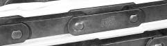 the dog is tilted forward, making it possible for the post to pass. Following the report has passed, the dog immediately returns to its authentic position.
three. Duck puppy
A duck dog applies stress on a conveyed report on the guidebook rail. In the position where the manual rail ends, the canine ducks (drops), leaving the short article at that place while passing below it.
4. Tilt duck dog
A tilt duck canine has the two the functions of the tilt dog and also a duck puppy. Since it travels on a guide rail, it maintains stress on a conveyed short article. Whenever a conveyed posting originates from the rear, the dog tilts to allow it to pass. On the position exactly where the manual rail ends, it ducks to leave the article at that position, though passing underneath it.
(b)Particular Rivetless Chain
The prior part describes that by combining with various attachments, the DK Conveyor Chains could be utilised for virtually all standard applications. This part describes the DK Specialty Conveyor Chains formulated based mostly over the Common Conveyor Chain. Specialty Conveyor Chains present enhanced form, dimension series and materials advantages that suit respective applications. They might be classified into 3 forms: Specialized Application Conveyor Chain, Water Treatment Conveyor Chain, and 3D Bending Conveyor Chain.
Conveyor Chain with  Attachments for Conveying Bulk Elements
Steady Flow Conveyor Chain and Chain for Dust Conveyor
A chain with blades is operated in the powder to bring about the powder to flow during the similar direction as the feeding course of your chain. This is certainly identified as a Continuous Flow Conveyor Chain. Precisely the same type of chain is additionally used in a related way for discharging the dust created by numerous dust collectors. We manufacture 25 styles of Conventional Conveyor Chains with blades, two forms of Block Chains with blades , respectively suitable for the a variety of properties of dusts and powders, and five chains with particular cast steel blades for conveying powders prone to result in dress in. The respective chains are designated as follows:
We manufacture constant flow conveyors and dust conveyors making use of the above chains with blades as common equipment. Check with us for additional specifics.
(a) Continuous Flow Conveyor Chain
Constant Movement Conveyor Chains are applied for our regular continuous flow conveyors. Depending on the conveyed subjects, the next 3 styles of attachments can be found. The basic chain is often either a Regular Conveyor Chain or perhaps a Strong H-type Conveyor Chain.
(b) Chains for Dust Conveyor
This chain is utilised for conveyors exclusively for carrying dust. Based on the application, the following three types are available:
1) Roller S Conveyor Chain for low density powder with Attachment B or B1 for U and LU Sort Dust Conveyors
two) Roller M Conveyor Chain for medium density powder with Attachment KL or KUL for DU, DU-S, LDU and LDU-S Kind Dust Conveyors
3) Block Chain for highly abrasive powder with KL or KUL attachments for DUB, DUB-S LDUB and LDUB-S Form Dust Conveyors
You will discover a number of variety for heat treatment and specifications to the conveyor chains. Unique therapies may be applied not only to the chain as a full but to just about every 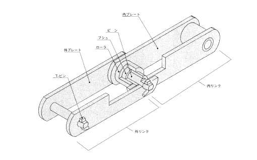 part individually, such as pins or plates only.
Decide on desired combinations in reference to the following explanation of attributes and uses.
Double Guard Coating
The surface is handled with outstanding corrosion resistant coating that approaches the resistance of stainless steel. Double guard coating includes double layers of two distinct supplies. It exhibits nearly doubled corrosive resistance inside the salt water spray test compared to our standard large guard coating, and can be used in mild alkaline or mild acidic disorders as much as pH3.
With its improved corrosive resistance, it could possibly be utilized in circumstances wherever high guard or plated coatings can’t be made use of, and also in some circumstances where only stainless steel can be employed.
(Double guard coating cannot be utilized to welded parts.)
Large Guard Coating
Substantial guard coated surface has exceptional corrosion resistance.
The surface of your chain is finished in non-gloss white extremely protective coating. It’s great resistance to salt corrosion and rusting. This coating protects chains in substantial temperatures as it can resist heat up to about 250°C.
Considering that substantial guard coating acts as being a sacrificial anode to the chain body, you could count on adequate corrosion resistance even when the coating has come off to some extent. Also, it may be applied to welded components.
It’s recommended for outdoor use or close to the sea in circumstances where overall performance as higher as that of stainless steel is just not required. In conditions that require resistance to alkaline and acid, double guard or stainless steel coating is proposed because they have far better resistance than higher guard.
Plating
Plating is generally carried out with nickel. It really is a coating with the two interesting exterior and corrosion resistance. By using it with grease lubrication, it exhibits exceptional corrosion resistance. You are able to expect the impact to delay hydrogen brittle destruction when utilized in conditions in which chains are exposed to sea breeze or acidic sprays.
(Double guard coating cannot be applied to welded parts.)
1.R-roller
R-roller Conveyor Chains have rollers with an outer diameter more substantial compared to the width of plates.
Since the rollers can effortlessly roll, the chain is ideal for running within the floor even though the rollers acquire the live load.
2.F-roller
F-roller Conveyor Chains have rollers with the similar outer diameter as that of R-roller but with flanges.
Since the flanges can acquire the force acting over the lateral sides in the chain, the chain is suitable for getting both a live load and also a lateral load.
3.M-roller
M-roller Conveyor Chains have rollers with an outer diameter slightly smaller compared to the width of plates.
An M roller is  made for smoother engagement with the sprockets. Since the chain is light in fat, it can be ideal for vertical conveyance.
four.S-roller
S-roller Conveyor Chains have rollers with an outer diameter smaller than that on the M-roller.
The chain is ideal for vertical conveyance the place rollers are significantly less prone to be worn.
5.BR- and BF- Rollers (with built-in bearings)
BR- and BF- Roller Conveyor Chains have typically identical framework to R-roller and F Conveyor Chains, respectively, except for your bearings within for smoother rotation.
six.UR- and UF- Rollers (large clearance concerning bushing and roller)
UR- and UF- Roller Conveyor Chains have primarily identical framework to R-roller and F Conveyor Chains, respectively. On the other hand, the clearances involving the outer diameter of bushings plus the inner diameter from the rollers are enlarged to stop the rollers from repairing when foreign matters enter.
DK Conveyor Chains are available inside a wide variety of dimensions, roller forms, and materials and heat treatment. Furthermore, the chains can be used for a broad array of application with our intensive variety of attachments and added features.
Classified by Dimensions
DK Conveyor Chains is often classified into standard, strong H-type and strong Z-type with reference to the dimension of the base chain.
The Common Conveyor Chain may be the fundamental form of DK Conveyor Chains, and many attachments, supplies, heat treatments, and so on. can be found.
The Powerful H-type Conveyor Chain was originally formulated like a chain for bucket elevators with enhanced strength and it is now out there in a series. A small-sized Solid H-type Conveyor Chain is almost equal in power to a large-sized Conventional Conveyor Chain, but since the dimensions and form differ, sprockets are not interchangeable. Typically, Powerful H-type Conveyor Chains are increased in strength than Typical Conveyor Chains with in regards to the very same roller diameter.
Solid Z-type Conveyor Chains are further enhanced in strength than Sturdy H-type Conveyor Chains by elevating the height with the inner plates, as well as sprockets are interchangeable if the nominal number would be the similar. Powerful H-type Conveyor Chains are utilized in machines through which the plates slide over the floor, this kind of as continuous flow conveyors, since the inner and outer plates have the identical height.
However, Strong Z-type Conveyor Chains exhibit high fatigue power and are used in vertical conveyor bucket elevators.
Classified by Roller Sort
The rollers of a conveyor chain perform not just to engage the sprockets moving the chain but in addition to rotate and travel on a rail, conveying articles or blog posts with modest frictional loss. To meet different shapes of rails and protect against meandering, etc., four sorts of rollers, significant roller, flange roller, medium roller and little roller.
In addition, for smoother rotation, we provide large rollers and flange rollers with built-in bearings (BR and BF rollers, respectively), and UR and UF rollers with massive clearances concerning the bushing as well as roller to stop the entry of foreign matters in to the bearings. These rollers are often used in waste processing amenities.
In this catalogue, huge rollers, flange rollers, medium rollers and tiny rollers are respectively expressed as R-roller, F-roller, M-roller and Roller S.
Once you style and design many conveyor systems utilizing little conveyor chains, the next basic situations need to be satisfied.
a. Chain tension: The real tensile strength in operation have to be drastically reduced compared to the specified strength from the chain.
b. Strength of loaded elements of chain: The actual loads applied to attachments, such as rollers of base chain, prime rollers, side rollers, and so on. in operation need to be substantially smaller than the strength of those elements.
c. Wear existence of chain: Lubrication disorders to make certain the put on daily life of chain must be fulfilled.
d. Sag adjustment of chain: The sag in the chain need to be kept optimum by tension adjusters, take-up units, guides, etc.
e. Others: Acceptable measures are taken to prevent rail put on, machine vibration along with other difficulties.
The next complement the above.
Calculation of Chain Tension
Normally, to start with, tentatively establish the chain dimension to be utilized referring to “Tentative determination of chain size”. Then, get “Theoretical chain stress (T)” (P213) for that tentatively determined chain, and multiply the worth by “Speed coefficient (K)”, to get “Substantial chain stress (Ta)”. For safety, the significant chain stress must be decrease than the “maximum allowable tension” stated inside the table of dimensions of respective chains. Consequently, the problem below needs to be satisfied.
Security condition of chain stress
Substantial chain stress (Ta) =Theoretical chain tension (T) ×Speed coefficient (K)
Substantial chain tension (Ta) <Maximum allowable tension
If this affliction isn’t content, pick a larger chain by one dimension and re-calculate.
Tentative determination of chain size
qDetermine the mass (excess weight) per unit length of elements this kind of as chain and attachment ωc (kg/m or kgf/m) assuming that it really is 10 % of your mass (excess weight) of your conveyed object ω1 (kg/m or kgf/m).
wIn reference to the calculation formulas on, acquire “Theoretical chain tension (T)” (kN or kgf) and “Speed coefficient (K)”, and calculate “Substantial chain tension (Ta)” (kN or kgf).
eIn reference to the table of dimensions of chains,determine the minimum chain, whose “maximum allowable tension” is greater than the  “Substantial chain stress (Ta)”, and regard it as “tentatively made the decision chain”.
Worth of pace coefficient (K)
The velocity coefficient (K) expresses the severity of operation ailment in accordance to the traveling speed of chain since the ailment gets severer as the traveling speed of chain becomes increased.
Multiply “Theoretical chain tension (T)” by “Speed coefficient (K)” to get “Substantial chain stress (Ta)”.
A DK conveyor chain includes a structure, plus the names in the components are stated during the drawing. These parts have functions specified below.
Pins
Pins help every one of the load acting on the chain together with plates, and once the chain is engaged together with the sprockets, they slide along with bushings as bearings. These are subject to put on and particularly must have large shear strength, bending power and dress in resistance. Hardened and tempered tough steel, carburized steel, or induction-hardened steel is made use of.
Rollers
Rollers secure the chain from shocks together with the sprockets, and when the chain is engaged with the sprockets, the rollers bend the chain smoothly and act to reduce the resistance when the chain runs on a rail. They can be necessary to possess substantial shock fatigue strength, collapse strength and put on resistance. Hardened and tempered hard steel, carburized steel or induction-hardened steel is used.
Bushings
Bushings are positioned in between pins and rollers and act as bearings for each the pins and rollers not to transmit the load obtained through the rollers right on the pins when the chain is engaged with the sprockets. They’re required to have substantial shock fatigue power, collapse power and put on resistance, and in general, carburized steel is applied.
Plates
Plates are subject to repeated tension from the chain and sometimes to massive shocks. They are expected to possess higher tensile strength, and especially higher shock strength and fatigue strength. Large tensile steel is utilized for regular chains and heat-treated alloy steel for heavy-duty chains.
T-pins
T-pins reduce the outer plates from disengaging from your pins. They’re manufactured from soft steel considering the fact that pins are usually pressed-in the outer plates and so no big force acts over the T-pins.
Single pitch chain
This chain is connected by hollow pins, and the hollows might be made use of to attach several attachments. In hollow pin chain, the hollow pins would be the same as the bushings in the corresponding standard chain in diameter, so hollow pin chain can be regarded as bushing chain that is made up of bushings  of your exact same diameter as that of the rollers with the corresponding regular chain.
Typical sprockets is often utilized.
The connecting back links are unique snap ring styles for hollow pin chain as illustrated.
Since no offset hyperlink is available, the number of links needs to be an even quantity.
Versatile Chain
Flexible Chain has good sideward bending versatility and it is ideal for curved traveling. Sprockets for JIS/ANSI Standard Roller Chain could be applied for this chain. By repairing attachments, this chain is often used for curved transfer with conveyors.
Flat Type Roller Chain
This chain is suited for conveyor techniques since it has flat plates that trigger minor injury to parts this kind of as chain guides. (The types of outer plates and inner plates would be the identical.)
Major Roller Chain
Loads can be straight placed over the top rollers. By attaching a stopper about the conveyor, loads might be temporarily stopped or stored whilst continuously driving the chain.
Side Roller Chain
This chain is utilised for a free of charge flow conveyor that runs on rails, along with the side rollers carry the fat of loads. Compared with Major Roller Chain of the same material, it can carry heavier load.
Hollow Pin Chain (HP)
The chain is connected with hollow pins that can be employed for fitting different attachments.
Flexible Chain (FX)
This chain has considerably sideward bending versatility and is appropriate for curved traveling.
Flat Plate Sort Roller Chain (F)
Harm to chain guards and other elements are lowered with all the use of oval-shaped flat plates, and loads may be set immediately to the chain.
Push Chain(PU)
That is the very first chain that has the ability to push. New layouts are possible because loads is usually pushed and pulled without utilizing the manual, and space can be saved in 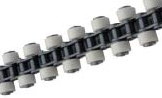 comparison to the use of cylinders.
In general, conveyor chains are operated for longer distances and at decrease speeds than transmission chains. Accordingly, though the pins, bushings and rollers are left unchanged, and the plate pitch is doubled to cut back the quantity of sprocket teeth engaged with the chain to half, the wear of pins, bushings and rollers is compact because the chain pace is reduced. Double Pitch Chains, conform to ANSI conventional and “Ultimate Lifestyle Chain Series” and “Environment Resistant Chain Series”, as are single pitch chains can also be out there.
Double pitch chain with resin rollers
This can be a Double Pitch Chain with R Roller manufactured from resin, which generates much less noise and lighter bodyweight compared with steel rollers. So, the chain is ideal for any conveyor system designed to operate quietly and convey light-weight posts. Because the elements apart from rollers are made from steel, the typical tensile power of the resin roller chain may be the identical as that of the steel roller chain. On the other hand, the “maximum allowable load” with the chain ought to be stored decrease, as shown while in the following table, to stop harm to your plastic rollers by the pressure from the engagement with sprockets.
The “Allowable load of resin rollers” refers towards 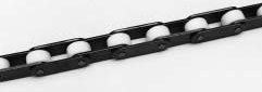 the allowable load acting when conveyed articles or blog posts press the resin rollers traveling to the floor surface this kind of as guid rails.
Massive roller (R) and smaller rollers (S)
Due to the fact double pitch chains are frequently used for conveying products on a horizontal floor, chains created for this function have enhanced roller diameter equal to that of single pitch chains in the similar pitch for increased load capacity and decrease traveling resistance. These rollers with larger outer diameter are referred to as “large rollers”, along with the frequent rollers are known as “small rollers”.
On this catalog, substantial rollers are expressed as R Roller, and little rollers as S Roller.
Designation of double pitch chains
A double pitch chain is designated, as while in the following instance, based on the nominal amount of the single pitch chain it is dependant on.
Connecting back links
For your connecting back links of double pitch chains of all sizes, the connecting plates and connecting pins are clearance-fitted. For C2060H or smaller, the spring clip type (R connecting hyperlink) is normal. For C2080H or more substantial, the cotter kind (C connecting website link) is common. Connecting hyperlinks with an attachment, top rated roller or side roller may also be accessible.
For ” Modest Conveyor Chains”, many backlinks are available for coupling and attaching custom devices immediately to the chains. These links are referred to as attachments. The following standard attachments are available.
Forms and names of typical attachments
regular attachments contain 5 kinds for single pitch chains and 5 kinds for double pitch chains as illustrated under. Furthermore, for single pitch chains, 4 kinds of wide attachments, as wide as outer plates, are available. Standard attachments for respective chain sizes are listed about the following page.
The best way to indicate the specially organized chains with attachments
A chain with Attachment K1s specially organized as over is indicated as follows:
CJ+(K1 inner+PL)×3+3LL+PL+(K1 inner+PL)×3+3LL+K1 outer+(RL+K1 outer)×2+5LL
“CJ” stands for a C connecting hyperlink; “K1 inner”, an inner hyperlink Attachment K1; “PL”, an outer hyperlink; “3LL”, 3 links from an inner link to an inner hyperlink; “K1 outer”, an outer website link Attachment K1; and “RL”, an inner link, respectively. A “+” signal suggests “connection”, in addition to a “×” indicator implies “repeat”. (For one-side attachments such as Attachment A and Attachment SA, the position of attachment plates is on side A within the above illustration.)
Note: When attaching attachments to every even-number link, they’re connected to outer links, unless 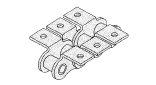 specified.
Ultimate Daily life Chain Series
Sound Bushing (HT/ T), (D)
1.Making use of higher precision sound bushings
2.Greater put on resistance than typical chains
3.Wear existence is improved by one.2 to four occasions of conventional chains
DH-|¨¢(DHA)
one.Ultra hardening coated  pin surface
two. Appropriate for conditions in which foreign substance contamination or intense oil degradation happens
three. Put on existence is improved by 1.two to seven times of typical chains
O-Ring (LD),X-Ring (LX)
1. Grease is filled involving pins and bushings.
2. High-end merchandise of Greatest Existence Chain that may be employed anyplace
three. Wear daily life is enhanced by 5 to 20 times of common chains
Sintered Bushing (UR), (URN)
one.Using sintered alloy for bushings
2.Long existence chain for low-speed and light load operation
3.Dress in life is enhanced by five times of normal chains
Nickel Plate(N)
1.Specialized nickel coating
two.Ideal for conditions requiring a clean impression and neat visual appeal
three.Withstands salt breeze and acidic problems
Surroundings Resistance Chain Series
Hi-Guard
one.High corrosion resistance coating
two.Appropriate for conditions the two indoors and outside the place long-term resistance to rusting is equired
3.Great resistance to corrosion, salt and rusting
Double Guard (WG)
1.Approx. twice extra corrosion resistant when compared to Large Guard Chain
2.Applicable in mildly acidic or mildly alkaline disorders
three.Downsizing is probable compared to Stainless Steel Chain
Stainless Steel Chain:SS
one.18-8 stainless steel
two.Appropriate for circumstances exposed to chemical agents, water or substantial temperature
3.Ideal corrosion resistance and heat resistance
Stainless Steel Chain:SSK
one.18-8 stainless steel (plate) + precipitation hardened steel (pin/ bush/ roller)
2.Ideal for areas exposed to chemical agents, water and large temperature
3.one.five instances more allowable stress in comparison with SS style
Stainless Steel X-Ring Chain (SSLT)
1.Excellent put on resistance
two.Excellent value overall performance
3.Important reduction in friction-loss
Lower Temperature Resistant Chain (TK)
one.Utilizing materials ideal for reduced temperature and specialized grease
two.Appropriate for circumstances wherever temperatures drop down to -40 ??C.
3.Excellent low temperature strength
When the engagement involving chain and sprockets turns into defective or any element that brings about excessive decline inside the power on the chain takes place, replace the entire chain. When any with the following ailments happen from the chain you utilize, replace the complete chain to sustain security.
Whenever a chain is worn near to the “Elongation restrict of chain” .
?When a flaw or crack occurs inside a plate.
?Whenever a flaw or crack or defective rotation of a roller is observed.
?When a chain hyperlink is stiff.
?Whenever a pin is rotated.
?When a pin is bent or otherwise deformed or whenever a plate is seriously warped.
?When rust buildup prevents smooth bending of the chain.
?When diluted sulfuric acid or every other corrosive material is 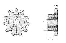 deposited.
Should you are unable to judge regardless of whether a flaw is “harmful”, please seek advice from us.
Substitute of sprockets and just how to purchase
The existence of sprockets is generally several occasions the daily life of a chain, but when the teeth are worn for the reason that of inadequate lubrication or damaged since of the shock load, and so on., the sprockets have to be replaced.
?When placing an buy, please specify the next should the chain No. is acknowledged.
one. Chain No. and amount of strands
two. Type of sprockets
3. Shaft hole diameter (d) (This can be not important for those who drill this hole; in this instance, drill a hole not exceeding the maximum shaft hole diameter.)
four. Number of teeth
5. Hub diameter (DH) and length (L) (in the case of non-standard sprockets)
six. Whether the tooth heads are hardened
Specify the next items, when the chain No. is unknown
1. Tooth thickness (T)
two. Root diameter (DB) (Caliper diameter (DC) while in the situation of odd-number teeth)
To get conscious aforetime of how and which aspect from the chain is damaged below improper use greatly assists to clarify the trigger and decide corrective measures in this kind  of an event.
?Fracture of plate.
Whenever a large tension acts to fracture a plate, as shown in (a), the lower ends are oblique and plastic deformation takes place. However, when the load is somewhat greater than the optimum allowable stress, fatigue fracture takes place. A substantial function of fatigue fracture is that a crack occurs within the path almost perpendicular to the pitch line (center line in between each pins). In the case of hydrogen embrittlement by an acid, the crack largely occurs within the direction as proven in (c), and the lower ends are flat, when the region around the lower ends could be decolored due to erosion from the acid.
?Fracture of pins
Whenever a pin is fractured by excessive tension, the fracture occurs close to the plate, by using a bulged specular surface formed by shearing. On the other hand,once the acting force is just not so solid, fatigue fracture requires area following an extended period of time around the center of the pin as shown in (e), as well as the fractured surface is flat with compact undulations.
?Fracture of bushings
As with rollers, bushings fracture by shock. Normally, as proven during the photograph, a vertical crack occurs and stops near the plates. 1 crack could also be superimposed on a different, resulting in the central portion to come off. Normally, it can be mentioned that a bigger crack is triggered by a bigger tension.
?Fracture of rollers
When a roller fractures during operation, generally vertical splitting happens as proven while in the photograph, and generally, pitch marks of fatigue extend in the within in the roller and cause splitting. If splitting happens all at when on account of a big stress, the result in can be recognized quickly since the split faces are usually not polished. If stress is excessive, the rollers are forcefully pressed towards the tooth faces of sprockets, in addition to a roller finish could possibly be cracked and deformed.
?Rotation of pins
As shown in the photograph, the rotation of a pin may be recognized by the deviance on the rivet mark around the pin head in the accurate place. In case the chain is disassembled, galling is identified involving pins and bushings in many cases. The lead to of galling is improper lubrication or excessive tension. When a machine continues to be out of use for any long period of time, rust might build among pins and bushings, resulting in the pin to rotate.
Elongation of chain
Generally, the elongation of chains involves the following three kinds;
1.Elastic elongation by chain stress
If a load acts on the chain, the respective parts of your chain are elastically deformed, resulting in elongation. In case the load is eliminated, the authentic length is restored.
2.Plastic elongation by chain tension
If a load in excess with the elastic restrict acts on the chain, plastic elongation takes place. In this case, even though the load is removed, the original length can’t be restored. Plastic elongation of chain may well diminish its performance. Substitute it devoid of delay.
3.Wear elongation of chain
Chains are topic to dress in due to the fact pins and bushings are worn by mutual make contact with. Just after use to get a lengthy time, the dress in seems as a rise of chain length. That is dress in elongation. Wear elongation is surely an vital issue for deciding the timing of chain replacement.
Necessity of lubrication
Inside a roller chain transmission, even when the chain and sprockets are intended to suit the service problems, bad lubrication inhibits keeping effectiveness and daily life to style specs. From the situation of a roller chain, the dress in reduction brought about under suitable lubrication is radically distinctive from that induced with out it. Troubles triggered as a result of insufficient lubrication incorporate the wear of pins and bushings, rough engagement with the sprockets, elevated noise, and breakage due to prolonged undesirable conditions. Proper lubrication is extremely crucial. Needs of lubrication and also the results of proper lubrication are listed under.
Collection of lubricant
Lubricant ought to be a mineral oil of excellent excellent. It’s crucial the lubricant incorporates no dust or foreign substance. By no means use waste oil. In case the ambient temperature is very very low (-10??C or reduced) or substantial (+60??C or increased), a specific oil is necessary. In this case, please consult our engineering department.
Lubricating factors
When the chain is immersed in an oil bath, oil penetrates each and every component with the chain. While in the case of guide lubrication, brush lubrication or drip lubrication, be sure that the oil sufficiently penetrates the portions of q and w from the following illustration.
Lubricate to the sag side of your chain, i.e., in the place indicated in the following illustration. Because the lubricant can be beneficial for rust prevention, coating the entire surface of your chain together with the oil is advisable.
Lubrication styles (Explanation of a, B and C within the tables of Drive effectiveness (kW ratings)
The allowable kilowatt ratings of chains proven in table with the drive functionality (kW ratings) is based mostly to the situation that any in the following lubrication is adopted.
Basic cautions for lubrication
Unless appropriate lubrication is carried out, chain fatigue will outcome earlier, triggering several challenges. Cautious inspection is necessary.
Inside the case of inadequate lubrication
In case the lubricant is exhausted, red rust is produced between the inner and outer plates, triggering dress in dramatically. Whenever a chain is disassembled soon after going underneath such situation, red rust is noticeable over the surfaces of pins, and also the surfaces are roughened, as proven in this photograph. (Usually, pins possess a mirror surface.) The lubricant must be utilized ahead of this transpires.
Do not use grease for lubrication !!
Will not use grease to lubricate your chains, since grease  will take too long to reach the inside by way of pins and bushings at ambient temperature.
In advance of lubrication, remove foreign substances and dirt in the chain as extensively as you can. If water is utilized for washing the chain, rapidly dry it to avoid rusting, then lubricate.
Inside the case of drip lubrication, oil bath lubrication or forced feed lubrication
Verify the next:
one. The lubricant will not be dirty.
two. The volume of lubricant is appropriate.
three. Lubricant is uniformly utilized to the chain.
Cautions
Dust contamination need to be prevented to retain dress in resistance. If temperature rises abnormally or even the chain squeaks, the oil may well be exhausted. Check to confirm the situation.
Verify
a.Verify the following before operation
Connected joint
Confirm the connection is adequate and that parts have no difficulty.
Verify that bending is smooth(from the situation of O-ring chain, bending is slightly stiff).
Chain sprocket attachment
Verify that there’s no significant flaw, rust or dress in.
Verify that sag is suitable.
Verify that no pin rotates.
Confirm that rollers rotate smoothly.
Confirm the chain engages together with the teeth of sprockets.
Interference
Confirm that there’s nothing interfering using the chain, or that absolutely nothing is most likely to interfere together with the chain or security cover.
Lubrication
Verify that the volume of lubrication is acceptable. (For the sum of lubrication, see the table of lubrication types.)
Driving and driven shafts
Confirm that the axial measurement and parallel measurement are correct.
Confirm the difference of sprocket planes is within the allowance.
Peripheral gear
Confirm that peripheral gear is put in properly.
b.Soon after confirmation and adjustment of your above a, install the safety cover, and switch about the electrical power to start out operation.
?It can be probable to the chain to become thrown need to it break.Don’t remain inside the route of rotation through operation.
Caution
Obstacles
?Obstacles may perhaps bring about breaking or fracturing which can scatter components and injure individuals nearby. Be sure you clear away all obstacles.
Abnormal noise
?Abnormal noise during operation can be a indicator of trouble. Instantly switch off the energy, and identify the lead to.
Flaws and rust
?If any significant flaws or rust is noticeable, it may trigger the chain to break and fracture and quite possibly injure folks close by. Verify the chain has no serious flaws or rust.
Sprocket
?If a sprocket is worn, the sprocket may possibly break, or even the chain may well ride over the sprocket, breaking it and perhaps leading to injury  to individuals nearby. Confirm the sprockets are usually not worn.
Gadgets that prevent accidents
?Install accident prevention products.
To prevent human injury brought on by scattered products, install safety units (safety cover, security net, etc.).
?Install an emergency stop device.
To prevent human damage as a consequence of unexpected overload, set up an emergency shutdown gadget such as a load controller or a brake.
Before trial operation
Verify the following on chain set up ahead of beginning operation.
?The chain the right way engages with the sprockets.
?The joints are typical. (The spring clips are the right way
installed and cotters aren’t bent.)
?The chain sag is correct.
?The chain is not really in contact with all the chain situation.
?The lubrication is correct.
Verify objects during trial operation
In case the chain can be manually rotated, rotate it to verify that there’s no abnormality just before starting up trial operation. Be alert to the following during trial operation.
?Regardless of whether there is abnormal noise.
In the event the chain contacts the chain case or in the event the chain heavily vibrates, abnormal noise happens. Examine the set up of chain situation and chain sag.
?Whether or not lubrication is typical in the course of operation.
Re-check the issue of lubrication.
Elongation limit of chain Restrict of Chain Sag
?Elongation restrict of chain
Even though sag adjustment is regular, excessive elongation with the chain could cause abnormalities much like these caused by sag failure that inhibit smooth transmission. In such cases, replace the chain. A guidebook for replacement according to chain elongation restrict is listed below. Even if only one link reaches the elongation limit, replace the whole chain with a new a single. Unless of course lubrication is regular, the chain will elongate quickly, leading to the aforementioned troubles. Study the contents of “Lubrication” in the subsequent area cautiously for performing good servicing.
?Elongation measuring strategy
one.To reduce rattling apart from a slight volume of play during the chain as a complete, tighten the chain lightly and measure the elongation.
Note: For an accurate measurement, measure the elongation from the chain applying a measuring load (specified by ANSI) to the chain.
2.As illustrated beneath, measure the inner length (L1) plus the outer length (L2) and get the measured length (L).
three.Then, receive chain elongation.
So as to cut down the measuring gap, measure the length of about six to ten backlinks.
Chain wear-elongation check out gage
Sag adjustment of roller chain
To implement a roller chain to get a longer period of time, suitable sag is a crucial element. In case the roller chain is over-tensioned, the oil film in between pins and bushings is misplaced, shortening chain existence and damaging the bearings. In the event the chain sags overly, the chain will vibrate or be seized from the sprocket. In about 50 hours (it differs based on the service conditions) following starting up the roller chain use, the chain will likely be elongated by about 0.1 percent in the complete length as a result of the conformability of respective contacts. So, change the sag at this time. Thereafter, if appropriate lubrication is maintained, the elongation are going to be negligible. Check out and alter the sag at appropriate intervals.
Optimum sag
On the whole, hold sag S at about 2 percent of span L, but during the situation described beneath, maintain it at about 1 percent.
Ways to adjust sag
Alter sag in the following techniques.
1.Adjustment from the center distance
two.Adjustment employing a tensioner or idler
three.Boost or lessen of pitch amount by offset link
four.By using an offset link, the total length of a chain could be enhanced or decreased by one pitch. However, because offset hyperlink overall performance is usually poor, an even variety of back links, if feasible, is suggested.
one.A connecting link of an O-ring Chain for standard application is pre-coated with grease at the pins. Ahead of connection, verify the grease around the surfaces of pins, and in the event the amount of grease is smaller, apply grease with bare hands. (If gloves are applied, the grease might be absorbed through the gloves.)
Illustration: When the connecting hyperlink (I) of an O-ring chain for common application is
shipped, O-rings are fitted at the roots on the pins. When the O-rings come loose on account of vibration through transport, refit the O-rings in on the roots on the pins.
In this case, be sure you return the grease collected at the roots of your pins to your central surfaces on the pins, extra at portion A than at portions B proven while in the over illustration. (Portions A is worn because of sliding together with the bushings.)
two.The chain might be most effortlessly linked around the teeth of a sprocket. Engage the backlinks at each ends with the chain using the sprocket teeth and match connecting pins. If the sprocket is often moved, the chain may also be linked over the loosened side.
three. Connecting process
one.Confirm that O-rings are attached towards the roots on the pins.
two.Should the quantity of grease applied within the connecting pins is modest, coat the pins with grease on the central portions.
3.Insert the connecting pins in to the bushings with the inner links at each ends.
4.Confirm the grease is applied to the total face with the O-ring, and match the O-ring onto the connecting pins.
five.Insert the connecting pins in to the connecting plate and even though pressing the connecting plate, set up the spring clip. Verify whether the head (the end with no split) in the spring clip is turned from the feeding 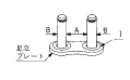 route from the chain. (See the next illustration.)
six.Make sure to verify the spring clip is securely fitted within the clip grooves in the connecting pins.
This completes jointing with the connecting link. Note that grease to the surfaces of connecting pins and O-rings might be removed for the duration of installation work. In this instance, re-grease using the grease to the surface with the base chain or the grease from the polyethylene bag in which the connecting website link was contained.
Installation of sprockets
For smooth transmission and extended daily life of your roller chain, it’s crucial that you the right way install proper sprockets. Utilize the following 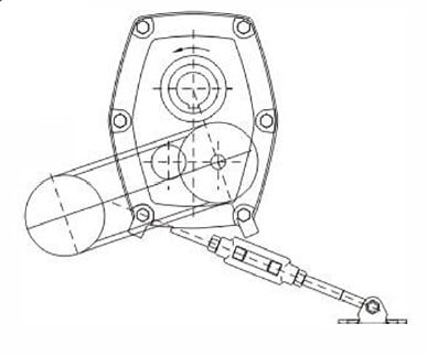 installation process.
one.Properly install a sprocket on a shaft, and correct it using a vital to stop it from rattling through operation. Also, location the sprocket as shut as is possible to your bearing.
2.Change the shaft levelness to ?¨¤1/300 or less using a level.
3.Modify the shaft parallelism[(A¡ê-B)/L]to ?¨¤1/300 or much less.
four.Adjust the level of driving and driven sprockets utilizing a linear scale. (Also modify the idler as well as sprockets, or even the tensioner as well as the sprockets inside the same way.)
Keep the allowance |? while in the selection specified.
Installation of roller chain
When connecting a roller chain with the sprockets, observe the next procedure. Once the connecting link will not be very well lubricated, apply sufficient grease.
When making use of the sprocket teeth
one. Engage the chain together with the sprockets so that the two ends of the chain are on on the list of sprockets, as shown during the following photograph.
2. Insert connecting pins at the joint.
three. Fit a connecting plate, and fasten by a spring clip or cotters.
Pay more interest not to damage the tooth heads of the sprocket.
When working with equipment
Cautions
1.Whenever a connecting plate is fastened by a spring clip,apply the spring clip on the pin grooves from the connecting pins as illustrated beneath, and lock it utilizing pliers, and so forth. As for the path of spring clip insertion, keep the opening of the spring clip turned during the path opposite towards the route of chain rotation, as illustrated below.
two.In situations in which the sprocket center distance can hardly be adjusted, an odd amount of links may be utilised. Even so, include one website link, to utilize an even variety of hyperlinks and eradicate the sag by shifting a sprocket or putting in an idler.
When an H-connecting website link is applied, pins has to be driven into the connecting plate simply because of interference. In this case, make sure that the pair of pins are kept parallel to just about every other when inserted into the connecting plate. Under no circumstances make the holes from the connecting plate more substantial or make the pins thinner for simpler connection function. This applies also when a cotter kind outer website link (CP) is utilized in place of a connecting hyperlink.
When a roller chain is applied, shaft positions is usually arbitrarily established. Having said that, in principle, follow the illustration proven beneath. That is definitely, when the chain is tensioned horizontally, hold the prime tensioned. Stay clear of vertical transmission when possible. In an inevitable situation, location the massive sprocket in the bottom regardless with the course of rotation.
When the chain layout is undesirable:
?Once the major is sagging and the sprocket center distance is brief:
As illustrated under, adjust the sprocket center distance shaft to do away with the sag.
?Once the top is sagging as well as the  sprocket center distance is lengthy:
As illustrated under, set up an idler from within to do away with the sag.
?Once the chain is vertical or inclined:
Get rid of the additional sag by a tensioner. In this instance, a tensioner that instantly eliminates the sag gives much better benefits.
When a pulsating load acts in higher pace operation:
The chain’s vibration and also the load influence frequency or chordal action may well synchronize to amplify vibration on the chain. Considering that vibration impacts the chain, consider countermeasures to avoid vibration from the following measures:
?Alter the chain pace.
?Increase chain tension. Even so, note that over-
tensioning can shorten the existence in the chain. ?Use an idler or tensioner to divide the span
?Install a guide stopper to prevent vibration.
Note: Chordal action refers towards the vertical motion of chain induced when it is actually engaged with sprockets.
Required length of roller chain
Utilizing the center distance between the sprocket shafts along with the number of teeth of the two sprockets, the chain length (pitch amount) may be obtained from the following formula:
Lp=(N1 + N2)/2+ 2Cp+{( N2-N1 )/2π}2
Lp : General length of chain (Pitch quantity)
N1 : Number of teeth of tiny sprocket
N2 : Variety of teeth of big sprocket
Cp: Center distance in between two sprocket shafts (Chain pitch)
The Lp (pitch variety) obtained through the over formula hardly turns into an integer, and ordinarily contains a decimal fraction. Round up the decimal to an integer. Use an offset website link in the event the variety is odd, but choose an even quantity as much as feasible.
When Lp is determined, re-calculate the center distance among the driving shaft and driven shaft as described inside the following paragraph. If your sprocket center distance can 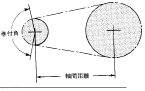 not be altered, tighten the chain working with an idler or chain tightener .
Center distance involving driving and driven shafts
Definitely, the center distance concerning the driving and driven shafts should be much more compared to the sum with the radius of the two sprockets, but normally, a proper sprocket center distance is regarded to get thirty to 50 occasions the chain pitch. However, when the load is pulsating, twenty occasions or much less is suitable. The take-up angle among the modest sprocket and also the chain must be 120°or much more. Should the roller chain length Lp is offered, the center distance between the sprockets could be obtained in the following formula:
Cp=1/4Lp-(N1+N2)/2+√(Lp-(N1+N2)/2)^2-2/π2(N2-N1)^2
Cp : Sprocket center distance (pitch quantity)
Lp : Total length of chain (pitch quantity)
N1 : Number of teeth of smaller sprocket
N2 : Variety of teeth of huge sprocket
This is often a chain variety technique taking deterioration of strength in relation to temperature into consideration. Please use ideal lubricant for your temperature at which the chain would be to be used. Seek the advice of us for specifics.
1. Effects of temperature on the chains
one.one Effects of large temperature
one) Increased wear induced by decrease in hardness
two) Increased elongation brought about by softening
3) Lubricant degradation, defective flexion caused by carbonization
4) Increase in dress in and defective flexion brought on by improvement of scales
two. Kilowatt ratings according to temperature
one.two Results of very low temperature
one) Decrease in resistance to shock brought on by lower temperature brittleness.
two) Defective flexion brought about by lubrication oil coagulation.
3) Defective flexion brought about by adhesion of frost and ice.
4) Rusting brought about by water-drops.
3. Chain Variety in accordance to Temperature
(Chain speed=50m/min or significantly less)
four. Use of Stainless Steel Chains (SS, SSK) at high temperatures
Stainless steel chains (SS, SSK) could be employed up to 400??C, but be aware that the ambient temperature and the chain temperature might vary. The strength of your chain decreases as the temperature rises. Specifically at higher temperatures, the greater the temperature rises, the chain will rupture by a decrease load (creep rupture).
In addition, defective flexion or defective chain revolution takes place on account of heat expansion. To be able to protect against such issues, alter the clearance involving chains. Consult us when making use of chains at 400??C or higher.
Chains are unable to be employed at 700??C or increased.
The description in this chapter may be applied whenever a chain is endlessly engaged for transmission with two sprockets parallel within their shafts and precise in Driven alignment as illustrated under.
1.Seek advice from us whenever a chain is to be employed for lifting, pulling dollies or staying engaged using a pin gear, etc.
two.When there are any regulations or tips concerning the collection of chains, choose a chain in accordance with such rules as well as the highest kilowatt ratings (Drive efficiency) table described under, and pick out the 1 that has a larger allowance.
The chain can be picked according to the next two procedures:
(1) Selection by drive effectiveness
(2) Low-speed variety
The drive efficiency method considers not only chain stress but also the shock load around the bushings and rollers as a result of the engagement in between the sprockets plus the chain, as well as dress in of pins, bushings and rollers.
The slow-speed process is applied when the chain is operated at a pace of 50 rpm or significantly less. Generally, the chain chosen by this strategy is topic to disorders more significant than that selected in line with the choice by drive performance. Consequently, thoroughly assess the circumstances when picking out with this particular method.
Selection by drive functionality
First, the next data is required.
1.Energy to get transmitted (kW)
2.Speeds of driving shaft and driven shaft (velocity ratio) and shaft diameters
3.Center distance involving driving shaft and driven shaft
(a) Correction of power to get transmitted (kW)
Correction will have to be manufactured to obtain the real energy to be transmitted as the level of load fluctuates depending on the machine and energy supply used, affecting the expected service lifestyle (such as, 15,000 hrs inside the case of capacities shown within the table of highest kilowatt ratings). The support element shown in Table 1 is an indicator of your load level. The electrical power to get transmitted (kW) is multiplied by the corresponding services component to acquire a corrected power.
Corrected power (kW) =
Power to get transmitted (kW) ×Service aspect
(b) Variety of chain dimension as well as the number of teeth of compact sprocket
Utilizing the table of maximum kilowatt ratings
Should the outcomes tentatively determined as described above are close to your style and design values, the amount of teeth of modest sprocket is often finalized with reference towards the table of highest kilowatt ratings. The maximum kilowatt ratings are established anticipating that an countless chain with 100 hyperlinks has a life of 15,000 hrs under the following circumstances. (That is certainly, the breaking in the chain along with the reduction of bushings and rollers tend not to come about at a wear elongation of 2 % or much less.)
one.Operation is carried out in ambient temperature (-10°C~+60°C) totally free from dust and dust-containing liquid.
two.There’s no corrosive fuel, or humidity, and so on. to adversely have an effect on the chain.
three.Proper lubrication is maintained.
four.The chain is employed below situations of a minimal start-stop frequency and a reasonably stable load.
From the case of multiplex chain
Decide on a multiplex chain when the capacity of a simplex chain is insufficient. The utmost kilowatt rating of a multiplex chain can’t be obtained by multiplying the utmost kilowatt rating of a simplex chain by the variety of multiplex chain given that the loads aren’t evenly distributed amongst the strands. To the correction element within this case, see the multiplex chain component table. Our normal HI-PWR-S Roller Chains and HI-PWR-SHK Roller Chains can be found up to triplex.
Remarks for figuring out the quantity of teeth of tiny sprocket
When a chain of the minimal chain pitch necessary optimum kilowatt rating is selected, reasonably silent and smooth transmission might be attained, as well as the products 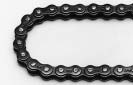 is usually compact.
Having said that, considering smooth chain transmission, the wear in the chain and sprockets, and so forth., it is actually desirable that the sprocket have 15 or much more teeth, and preferably an odd variety. Avoid 12 teeth, 14 teeth and sixteen teeth. When the sprocket has 12 or significantly less teeth, the chain and sprocket heavily vibrate and are really worn, and transmission is just not smooth. Likewise, keep away from a smaller quantity of teeth as much as achievable except in the case of reduced pace with no shock.
Shaft diameter
Following the variety of teeth of small sprocket is determined, multiply it by the velocity ratio, and verify no matter whether the demanded shaft bore could be secured in reference for the greatest shaft bore in the table of sprocket dimensions. In the event the expected shaft bore is bigger than the highest shaft bore, increase the number of teeth, or opt for a 1 dimension bigger chain.
(c) Choice of the quantity of teeth of huge sprocket
Once the variety of teeth of compact sprocket is established, multiply it by the velocity ratio to determine the number of teeth of significant sprocket.
In general, rising the sprocket teeth variety makes the chain bending angle smaller sized, which increases durability and enhances transmission efficiency. Even so, in case the number of teeth is too substantial, slight elongation tends to cause the chain to ride more than the sprocket, so maintain the utmost amount of teeth at 114 or significantly less.
Velocity ratio
A speed ratio refers for the ratio on the velocity in the driving shaft for the pace of your driven shaft, and ordinarily a speed ratio of seven:1 or much less is protected. When the velocity ratio is more substantial than this ratio, the take-up angle from the chain to the compact sprocket decreases, and chain jumping or abnormal wear of sprocket are likely to arise. If a large pace ratio is critical, two-step speed alter could be vital.
Low-speed choice
The low-speed assortment approach is applied when the chain operation velocity is 50 m/min or significantly less and there isn’t a be concerned of dress in elongation and shock fracture of rollers and bushings.
In low-speed choice, the chain is selected in reference towards the tensile fatigue strength from the chain. For that reason, a chain picked according to this technique will probably be subject to extra significant situations than 1 selected according to the variety by drive functionality approach. When the Low-speed selection method is made use of, special care ought to be exercised. The Low-speed assortment method cannot be made use of for that connecting links and offset links.
(a)How to receive corrected chain tension
Corrected chain tension=Maximum stress acting on chain kN (kgf)×(service factor)
To determine the corrected chain tension, identify the precise optimum tension acting over the chain. The shock is regarded as to some extent inside the service factor, nonetheless it is not really absolute. Also contemplate the enhance of stress by the inertia of tools brought on by commencing and stopping.
(b)Comparison with the optimum allowable tension of chain
Using the utmost allowable tension within the table of chain dimensions, sprocket tooth issue and rotating aspect on the smaller sprocket listed beneath, receive the corrected maximum allowable tension from your following formula:
Corrected highest allowable tension=(Maximum allowable tension)×(Sprocket tooth factor)×(Rotating factor)
If your corrected maximum allowable stress is bigger compared to the corrected chain tension, you’ll be able to decide on the chain. For the amount of teeth and pace of little sprocket not stated in Table 1 or 2, acquire the sprocket tooth factor and rotating component by linear interpolation.
Sprockets could be classified into typical sprockets, HK sprockets along with other sprockets.
1. Regular sprocket
Conventional sprockets are ANSI sprockets which can be engaged with normal series roller chains. See P125 for dimensions.
You can find two varieties of tooth profiles: U-tooth and S-tooth.
2. HK sprocket
HK sprockets is usually engaged with HK series roller chains, and people for single strand chains are identical to conventional sprockets. Having said that, sprockets for many strand chains are diverse from typical sprockets in sprocket tooth profile.
3. Other sprockets
Other sprockets are intended in accordance to your following calculation formulas to suit respective specialty chains.
The sprockets made use of for that following chains will be the exact same since the normal sprockets in tooth gap form, but different in tooth thickness (sprocket tooth profile).
four. Calculation of sprocket dimensions
The dimensions of regular sprockets and other standard sprockets are calculated as follows. At first, the diameters of sprockets are calculated in the following calculation formulas.
Upcoming, sprocket tooth profile (the form with the tooth according to its thickness) is calculated through the following calculation formulas. (The values shown from the following pages have been calculated by these formulas and thought to be the conventional values.)
Calculation formulas for diameters and tooth gap kinds Calculation formulas for diameters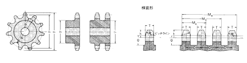 Calculation of pitch diameter, tip diameter and caliper diameter
The essential dimensions of a sprocket ideal for any chain pitch of one mm are respectively known as pitch diameter factor, tip diameter element and caliper diameter component. The respective aspects for respective numbers of teeth are listed beneath. If these aspects are multiplied by chain pitch, the essential dimensions with the corresponding sprocket can be obtained.
Instance:
While in the situation of 80 (25.forty mm pitch) with 35 teeth Pitch diameter (Dp) = P×Pitch diameter issue
Calculation formulas for tooth gap types
Because the most rational tooth gap forms by which the strain angle alterations in response for the elongation of a smoothly rotated roller chain with the lapse of service time, ANSI specify two kinds of tooth profiles: U-type and S-type. Generally, S-type tooth profiles are adopted in accordance with ANSI, and our standard sprockets also have S-tooth profiles.
This gage checks the wear-elongation of chains.
Test the chain elongation at a portion that’s most
regularly engaged using the sprockets (portion probably to become worn).
When the center of the pin from the chain to become measured
This gage checks the wear-elongation of chains.
Check out the chain elongation at a portion which is most
frequently engaged using the sprockets (portion probably to become worn).
When the center with the pin from the chain to get measured reaches the arrow level, it implies that the chain has been critically elongated. In this instance, change the chain.
Use the gage to examine the dress in elongation of one’s chain.
Common terms for sprockets
Nominal number of sprockets
The nominal number of a sprocket would be the similar as the nominal variety of the corresponding chain. Such as, Chains this kind of as 50, 50HK, and 50LD can be engaged using a sprocket 50. It truly is followed by symbols and characters indicating the amount of chain strands, the amount of sprocket teeth, hub kind, tooth head hardening, and so on.
Diameter of ready hole and shaft hole finishing
A conventional sprocket to get a single strand or double strand chain includes a shaft hole ready at a diameter stated during the table of dimensions. When you finish the shaft hole, machine it in reference for the outer diameter or root diameter.
Hardening of tooth heads
The teeth of a sprocket needs to be challenging and wear resistant because they are impacted when engaged with the rollers with the chain and worn by sliding with the rollers. When extreme dress in and large shocks are anticipated, sprocket.
Kinds, construction and elements
made from carbon steel or cast steel need to be utilised and high-frequency hardening really should be performed.
The regular sprockets 40 to 120 with a hub on just  one side for single and double strand chains are induction-hardened even if the amount of teeth is modest. No matter if the merchandise is induction hardened or not is proven while in the tables of dimensions of respective sprockets for your reference. On top of that, from the following circumstances, induction-harden the teeth of your sprocket.?The smaller sprocket has twenty or significantly less teeth and is applied at 1/6 or additional in the maximum velocity stated in the table of optimum kilowatt ratings.
The modest sprocket is utilized at a adjust gear ratio of 4:1 or extra.
The smaller sprocket is utilised to get a very low velocity big load transmission as in situations of selection according to the “Low-speed selection”.
Sprockets are used in situations in which the teeth are heavily worn.
Sprockets are applied under circumstances exactly where you can find frequent starts and stops or sudden typical or reverse rotations.
Basic cautions
For selecting the amount of teeth and pace ration of the sprocket, see “How to pick good chain” . For cautions for putting in a sprocket on the shaft and replacement timing, see “Installation adjustment maintenance” .
C-Top is usually a plastic cover for chains that may be conveniently attached. It’s ample load power for chains conveying items. As opposed to typical plastic chains, it could possibly be utilized underneath high tension as stainless steel chains. It is a perfect option to the use that requires the strength of steel chains free of charge from worries of damaging, soiling, and jamming of items. It also prevents operators from becoming caught through the chains. It can also be employed because the cover for chains employed for elevating products this kind of as multilevel parking machines.
Applicable chains
Is usually connected to chains corresponding to ANSI #40, 50, 60.
Sprocket teeth variety
Use sprockets with twelve or far more teeth.
Check out the outer diameter from the hub.
Shade
The common shade for this products is blue gray. Other colours is often supplied determined by the quantity.
Chain Lube (420 ml)/ HI-PWR Lube (330 ml)
Chain Lube is a spray type lubricant that was formulated specifically for chains. It has exceptional features that lengthens the chain lifestyle avoiding it from sporting and maximizes the chain’s transmission efficiency.
Applications
?Roller Chains for Electrical power
Transmissions
?O-ring chains
?Leaf chains
?Common conveyor chains ?Motorbike chains
?Bicycle chains
?Sprockets
Functions
?Very good adhesion and significantly less splatter. ?Very good lubricity to boost put on
resistance.
?Fantastic penetration.
?High corrosion prevention result. ?Superior water resistance and unlikely
to get washed away by water.
?Superb heat resistance.
?Does not impair the O-rings.
Leaf chains include pins and plates only and therefore are increased in power than roller chains. They are really suitable for duties like hoisting and pulling. Leaf chains conform to ANSI and have two forms: AL and BL.
AL style
For your use that static load is applied with very little concern of sporting.
BL variety
For that use that wear resistance is required considering the fact that effect load is utilized.
Variety of leaf chains
The chain dimension is picked according for the following formula:
Acting tension?¨¢Service factor¡§QMaximum allowable stress Notes:
1. Acting tension consists of the dead bodyweight with the chain, the fat on the attachments and inertia.
2. In the event the chain speed exceeds thirty m/min, use a roller chain.
Minimal sheave diameter: S.D = Chain pitch?¨¢5
Minimal width between flanges: L = All round length of pin?¨¢1.05
?If connecting pins are offered: L¡§R2L1?¨¢1.05
F.D = S.D + Greatest website link plate height (H) Note:?If dimension H exceeds 25.four,
F.D = S.D + 25.four may be adopted as the minimal flange outer diameter.
Periodical inspection and instructions for replacement
You’ll want to carry out periodical inspection and lubrication to verify safety and prolong chain existence. Problems and directions for option are outlined from the following.
Problem:Circumferential dress in of plate
Solution:Exchange the chain if wear loss becomes 5 % of H.
Trouble:Oblique wear of plate and pin head
Solution:Align the unit.
Issue:Abnormal protrusion or rotation of pin head
Option:Substitute the chain Lubricate and get rid of overload.
Issue:Dress in elongation
Alternative:Change the chain when its length turns into 1.03L. Note: Dress in elongation of the
chain lowers its tensile power.
Dress in elongation of 3% lowers the tensile power by 18 %.
The dress in daily life of chain may be enhanced by lubrication. Substitute the chain.
Problem:Cracked plate (one)Crack: Through the hole of the link plate towards the end from the website link plate from the direction perpendicular to stress course.
Solution:Replace the chain which has a chain of increased highest allowable stress, or lower the load or dynamic (shock) load.
Issue:Cracked plate (two)Crack: In an oblique direction against tension route.
Alternative:Replace the chain, and secure from corrosive conditions.
Challenge:Broken plate(by high tension)
Remedy:Replace the chain, and eradicate the result in of overload.
Difficulty:Enlarged plate hole
Resolution:Exchange the chain, and reduce the result in of overload.
Difficulty:Corrosion of pit
Resolution:Replace the chain, and guard from corrosive circumstances.
SC silent chains (SCA, SCR, SC)
SC silent chains use specially-coated round pins and specific plates to attain an ideal engagement mechanism, and might preserve 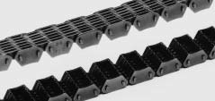 a noise level remarkably reduced than traditional roller chains.
SC sort silent chains could be used for substantial pace and significant tension transmission much like a toothed metallic belt since the plates straight engage with the sprockets for driving.
SCR-04 silent chains are designed with inner engaging construction for more decreased noise level.
PS silent chain
A PS variety silent chain features a framework by which a set of specially formed connecting pins and locker pins get hold of just about every other though rotating at each flexible bearing position. So, it generates significantly less heat especially in higher speed operation and it is excellent in durability. On top of that, the specially formed pins significantly reduce shock once the chain is engaged with sprockets, offering a larger silencing result than SC silent chains.
Sprockets
Sprockets for silent chains adopt specific modules in involute tooth kinds for your SCA 04××, SC 25××, SC 06×× around the earlier page and PS silent chains to make sure silent higher pace operation. For all sizes, the sprocket tooth heads are frequently hardened by induction hardening or carburizing.
As a result of very high technical demands derived from the 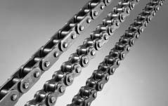 growth in the car sector, speedy strides were manufactured inside the development of engine mechanism chains this kind of as timing chains for driving cam shafts on 4-cycle engines used in motorcycles and motor autos, chains for driving oil pumps, generators and other auxiliary machines, and chains for driving balancer shafts. We have planet class technical skills within this location. The engine mechanism chains have great put on resistance, fatigue power, silencing effect and shock power capable of withstanding high pace operation, and can meet the conditions demanded for today’s potent however down-sized large overall performance engines. For silent chains, see the area for silent chains on this catalog.
The values of max. allowable load will not be utilized to connecting links. Don’t use connecting backlinks in engines.
The smallest chain complying to ANSI is 25 of 6.35 mm pitch. Even so, in response towards the demands for smaller chains in recent times for substantial technologies machinery such as workplace gear, health-related machines and industrial robots, we supply 15 of four.7625 mm (3/16 inch) pitch as well as 15H1 being a high-power model of 15. These large precision chains are manufactured underneath extreme top quality handle primarily essential for modest sizes, taking wear resistance also into account.
Variety of chain
Refer to your “Low-speed selection”. Nevertheless, the chain operation velocity can be set substantially high dependant upon the sort of lubrication as proven while in the table beneath.
Connecting backlinks and offset backlinks
R connecting links are applied for small pitch chains. However, since their strength is reduced than that on the base chain, and since the clip is likely to come off in higher velocity operation, the usage of connecting back links isn’t proposed. Use a loop chain without the need of attaching connecting hyperlinks.
Offset hyperlinks are available for chains besides 15 and 15H1, but their use will not be encouraged for that similar cause as stated for your R Connecting backlinks.
Operating velocity and sort of lubrication
15: A large precision mini-pitch bushing chain that is definitely smaller sized than a compact drive chain for basic applications, 25
25: Smallest bushing chain among ANSI typical chains utilizing curl bushings.
35: A ANSI standard bushing chain ideal for smaller precision machines that require substantial power.
Bicycle Chain
Bicycle chains are emblematic of your DID brand, and we were founded initially for the manufacturing of bicycle chains. They’ve got been employed in many bicycles made in Japan and worldwide countries.
Not too long ago, our Hi Guard Chain (E) with an extra rust preventive treatment has favorable popularity by end users. The bicycle chains are constantly examined and improved in overall performance, excellent and specs as viewed in the availability of current items. Being a outcome, they can be the lightest and most compact chains among solutions with the exact same size. Presently, they may be employed not merely for bicycles but for many purposes such since the driving of vending machines and agricultural implements and for conveyor systems.
Responding to various type of wants
Bicycle Chain
one.Rustproof handled Hi-Guard
(E) out there
2. Lightest of your very same size designs
Smaller Pitch Chain
1.Ultra-precise chain
2. four.7625 mm pitch out there
3. For high-tech machines
Engine Mechanism Chain
one.Camshaft drive timing chain
2.Drive chain of attached units
(oil pumps and so on)
three.For substantial efficiency engines
Silent Chain
1.Best engaging structure
2.High-speed sturdy tensile transmission feasible three.Higher noise reduction
Silent Chain
one.Larger durability in contrast
to SC
2.More substantial noise reduction when compared with SC
Agricultural Roller Chain
1.Very put on resistant
2.Remarkably heavy-load resistant
three.Very shock load resistant
BS Roller Chain(ISO B-series roller chain)
1.Complying with ISO “B series”standard
two.Complying together with the British and German Requirements
three.Sprockets comply with the British Regular.
Leaf Chain
1.Composed of pins and plates only.
two.Increased power when compared with roller chains
three.Two kinds are available: AL and BL.
Moreover to general chains, we also manufacture several chains produced for precise applications this kind of as bicycle chains and motorbike chains.
Some specialty chains is often engaged with standard sprockets. Put on resistant properties of common chains are included while in the specs of each form of specialty chains.
Specialty chains are classified as follows:
?Bicycle Chain
?Smaller Pitch Chain
?Engine Mechanism Chain
?Silent Chain
?Agricultural Chain
?Leaf Chain
?BS style Roller Chain (British Conventional Roller Chain)
Unparalleled noise reduction
Super Minimal Noise Chain (UN) has attained a greater drive efficiency although acquiring equivalent noise reduction functionality to Previous Minimal Noise Chain (TB). By enhancing the drive functionality to your amount of regular roller chains, Lower Noise Chains are now applicable to lots of a lot more machines and tools.
one.Noise reduction equivalent to Earlier Low Noise chains
The noise emitted when the chain engages with the sprockets may be decreased by approx. 10dB. For conveyor chains, sliding noise of the rails as well as rollers can be lowered likewise.
two.Durability equivalent to regular chains
The chains exhibit durability higher than Preceding Very low Noise chains and on the identical level as standard chains.
?Common connecting links and sprockets can be employed. Offset backlinks are specialized.
?Preventing partial wear of sprockets and rails
Compared to Past Reduced Noise chains, the steel rollers with the Super Lower Noise are in staggered assembling within the traveling course to reduce partial dress in of the sprockets and rails.
Super Minimal Noise Chain (UN)
A brand new reduced noise chain with unparalleled noise reduction
Super Low Noise Chain (UN) has accomplished a greater drive effectiveness whilst acquiring lowered noise like Preceding Lower Noise Chain (TB). By improving the drive overall performance 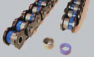 on the degree of typical roller chains, Low Noise Chains are now applicable to many far more machines and tools.
Attributes
?Super Lower Noise Chain was designed in response to your desires to get a wider application of minimal noise chains by modifying the triple-layer roller construction on the TB Chain right into a double layer roller. Noise reduction level is equivalent to that of TB Chain.
Suggested utilizes
?Conditions requiring the drive performance of
chains at the noise degree of belt conveyors
?Printing machines, packaging machines, workplace appliances and so on.
Noise reduction comparison
There is certainly about 10dB noise reduction to your noise from when the chain engages with the sprockets. (Fig. under) The sliding noise in the rails as well as the rollers is usually decreased too.
Super lower noise chains can be found up to 5 strands.
Sprockets, connecting links and offset links
Common sprockets and connecting back links can be utilised. Offset back links can also be available.
It really is proposed to make use of the sprockets with teeth of odd numbers and even numbers indivisible by four to engage them together with the chain rollers.
Caution
The rollers are made from risen and their effectiveness deteriorates when exposed to ultraviolet (UV) rays. Moreover, will not use in conditions wherever the resin roller are exposed to sprays and vapors of substances listed below:
Nonflammable hydraulic oil (phosphoric esters, water-glycol fluid), oils containing extreme-pressure additives, scorching water, vapor, ester, ketone, organohalogen, pure aromatic compounds, sturdy acid, solid essential agents, strong acidic reagents, carbon disulfide, sulfur dioxide.
The applicable situations are equivalent to these of conventional roller chains.
The corrosion resistance towards water, acid, alkaline, and also other chemical substances may also be equivalent to that of standard roller chains.
Stainless Steel Chains
using the attributes of environment resistant and put on resistant chain series. 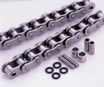 With the use of X-rings, durability enhanced remarkably.
X rings were added to your Stainless Steel Chain (SS)
which has the very best resistance to corrosion and heat. When compared with the typical Stainless Steel Chain,this chain has about 5~10 times resistance to abrasion.This improvement can make possible a significant reduction during the operating and maintenance costs.
Recommended utilizes
?Circumstances constantly exposed to chemical agents, sea water and wastewater.
Numerous chemical plants, water remedy plants
?Ailments of large temperature
Heat-treating furnaces, dry furnaces, incinerators
The grease and seal rings meet the specifications of your Food Sanitation Law.
Check with us in regards to the environmental disorders and chain selection.
Variety of chains
The typical tensile power and maximum allowable load on the Stainless Steel Chain are the two decrease than a common roller chain. Refer towards the optimum allowable load for your choice of chains.
Connecting hyperlinks
R connecting links are used for Stainless Steel Chains #60 or smaller and C connecting back links for #80 or larger.
Sprockets
The pins for the X-Ring chains are longer than these of normal roller chains, and hence regular sprockets for multiplex chain are not able to be used for that X-Ring chains when employing this chain in multiplex.
Caution
As being a common house of stainless steel, tension
corrosion cracking and pitting corrosion could be induced by chlorine and chlorine ion (CR-).
Please get into consideration the circumstances, temperature, level as well as other total circumstance when applying.
Excellent resistance to corrosion and heat that enables use in nearly all over the place
You will find two varieties of Stainless Steel Chain: SS and SSK. The SS sort has the highest resistance to corrosion and heat. Nevertheless, it can be produced fully of austenite stainless steel and as a result its tensile strength is slightly reduced than 70% of a regular roller chain, and highest allowable load drops to slightly more than 10%.
By utilizing precipitation hardened stainless steel for the pins, bushes and rollers, the SSK style has 1.five times greater maximum allowable load compared to the SS type. Pick SSK once you want much more power than SS, or wish longer products lifestyle.
The two types have equivalent corrosion resistance.
Proposed uses
?Circumstances exposed to mild alkaline and mild acidic
chemical agents, sea water and wastewater. Different chemical plats and water treatment method plants.
?Disorders of high temperature
Heat-treating furnaces, dry furnaces, incinerators
Choice of chains
Stainless Steel Chain has lower regular tensile strength and optimum allowable load in contrast to the standard roller chain.
Connecting back links and offset hyperlinks
R connecting backlinks are applied for Stainless Steel Chains #60 or smaller sized and C connecting backlinks for #80 or bigger. 2POJ offset hyperlinks are employed for sizes #25, and OJ links for all other sizes.
Sprockets
Regular sprockets for Stainless Steel chains may be utilised because the dimensions will be the identical as standard roller chains.
Caution
As being a general residence of stainless steel, pressure corrosion
cracking and pitting corrosion might be brought about by chlorine and chlorine ion (CR-).
The chart on appropriate displays the information of tests within the amount of corrosion resistance for each medium and doesn’t ensure the performance of the chains. Please think about the situations, temperature, degree along with other general problem when making use of.
Steel chain approaching stainless steel chain in corrosion resistance
Double Guard Chain is extremely corrosion resistant with coating of double layers of two distinctive materials. When compared to the High-Guard Chain, it exhibits almost doubled corrosion resistance while in the salt water spray check, and can be utilized in mild alkaline and mild acidic 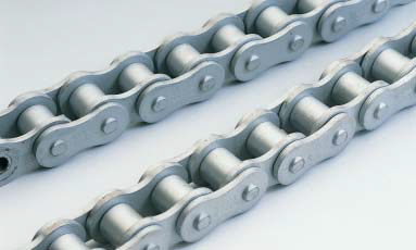 disorders.
Attributes
?With its enhanced corrosion resistance, it may possibly be used in situations wherever High-Guard or Rustless Chains cannot be applied, and also in some conditions in which only stainless steel could be used.
?The coating includes environmentally friendly non-chrome materials. To comply together with the EU’s Restriction of Hazardous Substances (RoHS) Directive, hexavalent chromium isn’t applied.
Recommended employs
?Circumstances that require each strength and corrosion resistance
Multilevel parking facility, moving decks, cleansing lines and so on. ?Situations exposed to rain or sea water
Machines installed outdoors, amusement machines
?Disorders exposed to mild alkaline and mild acidic chemical agents, sea water or wastewater. Various chemical plants and water remedy plants.
Choice of chains
Double Guard Chain has an equivalent power to a conventional roller chain.
Connecting back links and offset hyperlinks
R connecting hyperlinks are used for high-guard chains #60 or smaller and C connecting backlinks for #80 or greater, and OJ and 2POJ are utilised as offset links.
Sprockets
Regular sprockets for high-guard chains could be utilized since the dimensions will be the similar as standard roller chains.
Caution
Use stainless steel chains if your chains will can be found in direct get hold of with food.
Double Guard chain doesn’t have a gloss like the nickel coated chain.
Except if not so specified through the purchaser, chains are coated with grease and shipped. If attainable, oil the spaces in between pins and bushes and bushes and rollers. Please use the advisable lubrication oil for the maintenance on the chain as oiling with grease may cause flexion failure.
Hugely protective coating that goes far past the overall performance of nickel plating
Hi-Guard Chain has increased corrosion resistance subsequent to stainless steel chains. The surface with the chain is finished in non-gloss white hugely protective coating. It has excellent resistance to anti-corrostion and rusting. It has equal power to regular roller chains, and might be used in situations the place power increased than that of stainless steel chains is required.
Characteristics
?Considering 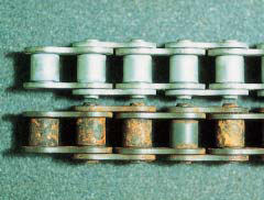 that large guard coating acts being a sacrificial anode for your chain body, you may assume adequate corrosion resistance even if the coating has come off to some extent.
?The coating includes environmentally friendly chromium no cost material. To comply using the EU’s Restriction of Hazardous Substances (RoHS) Directive, hexavalent chromium just isn’t employed.
Advised uses
?Applications need each power and corrosion resistance
Multilevel parking facility, moving decks, cleansing lines etc.
?Circumstances exposed to rain or sea water
Machines set up outside, amusement machines
Choice of chains
Higher Guard Chain has power equivalent to regular roller chain.
Connecting back links and offset back links
R connecting backlinks are utilized for Large Guard Chains #60 or smaller sized and C connecting hyperlinks for #80 or greater. 2POJ offset back links could be employed for sizes #25 and #35, and OJ and 2POJ for all other sizes.
Sprockets
Regular sprockets for High Guard Chains is often made use of since their dimensions will be the same as individuals of standard roller chains.
Caution
Use stainless steel chains in the event the chains can be found in direct make contact with with meals.
Higher Guard Chain isn’t going to possess a gloss like the plated chain.
High-guard coating has exceptional standard corrosion resistance, but has poor alkaline and acidic resistance.
Except if not so specified by the client, chains are coated with grease just before delivery. If probable, lubricate the spaces concerning pins and bushings and bushes and rollers. Please use the advisable lubricant for your servicing of the chain due to the fact lubrication applying grease can cause flexion failure
Specialized nickel plating to get a neat and clean appearance and corrosion resistance
The surface of Rustless Chains is nickel plated for an interesting exterior and corrosion resistance. It is going to exhibit exceptional corrosion resistance particularly when utilised in blend with grease lubrication. You could count on the effect to delay hydrogen brittle destruction when employed in situations in which chains are exposed to sea breeze or acidic sprays.
Characteristics
?The chain is protected even if in use with gilding or alumite machines that emit corrosive steam.
The effectiveness of rust resistance and corrosion resistance of the nickel plating doesn’t deteriorate even underneath conditions of high temperature and continues to guard the chain.
?The chain’s fine exterior 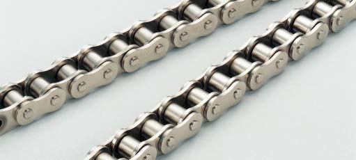 tends to make it best for machines for demonstration.
Suggested employs
?When a clean visual appeal is preferable
Meals sanitation machines, office machines, textile machines, printing machines, pulp processing machines etc.
?When working with inside a corrosive atmosphere Chemical machines, gilding machines, alumite machines
?Whenever a neat exterior is critical Demonstration machines at exhibitions etc.
Choice of chains
The power of Rustless Chain is equivalent with conventional roller chains.
Connecting backlinks and offset backlinks
R connecting back links are employed for Rustless Chains #60 or smaller sized and C connecting hyperlinks for #80 or more substantial. We offer 2POJ offset backlinks for sizes #25 and #35, and OJ and 2POJ for all other sizes.
Sprockets
Regular sprockets for Rustless Chains could be employed because the dimensions would be the similar as normal roller chains.
Caution
Please use stainless steel chains once the chains are to get regularly exposed to water, sea water, liquid remedies or corrosive options.
Unless of course wot so specified through the buyer, chains are coated with grease in advance of delivery. Please make use of the suggested lubricant for that servicing on the chain considering that lubrication using grease can cause lubrication failure.
Talk to us in case the chain is always to be employed for hoisting applications.
Servicing free chains employing sintered alloy bushings
Sintered bushing roller chain is maintenance-free chain ideal to a spot wherever lubrication is complicated. It uses bushings created of the sintered alloy which impregnates lubricating oil.
For that use that requires clean visual appeal, rustless sort (URN) is obtainable.
Recommended makes use of
?Conditions the place lubrication is hard or elongation of chain frequently happens Remarks for use.
?Do not use this chain in dusty environments. 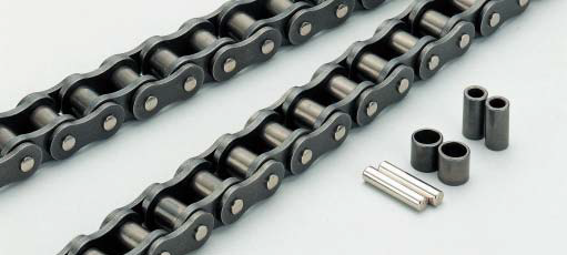 In such environments, use O-ring chains.
?This chain is for your use under light or medium load.Use O-ring chain when a large effect is utilized to a chain.
?Set the chain feeding velocity at 150m/min. or reduce.
Choice of chains
As for sintered bushing roller chains, the inner plates are thicker as well as the pins are longer than those of typical roller chains in order to compensate for that power lowered by the use of sintered bushings.
For deciding on a suitable chain, refer to “Selection of Chains”. Use the tables of highest kilowatt ratings for sintered bushing roller chains that cover lower speed ranges.
For sintered bushing roller chains, “Low-speed selection” can not be utilized because the “Maximum allowable load” inside the dimension table considers only the chain tensile stress and neglects the bushing power.
Connecting hyperlinks and offset links
For sintered bushing roller chain, R connecting hyperlinks are used for DID60 or smaller, and C connecting backlinks for DID80 or larger.
OJ could be utilized as offset backlinks. Please spot an order the connecting hyperlinks and offset back links specifying the form for sintered bushing roller chain.
From the tables of greatest kilowatt ratings, the strength on the connecting back links and offset backlinks are taken under consideration.
Sprockets
Regular sprockets may be applied for sintered bushing roller chains.
Highest dress in resistance offered by  sealing grease in between pins and bushings
The sturdiness of chain is radically improved considering the fact that grease is sealed between the pins and bushings by O-rings. The O-ring chain will be the most dependable model of your Ultimate Existence Chain Series with its exceptional wear resistance even inside the problems or environments where chain upkeep is difficult.
Advisable employs.
?Situations wherever frequent chain replacement is required due to put on stretch
?Circumstances exactly where lubrication throughout the services is unattainable
?In an natural environment with a lot soil, sand, dust, and so on.
?Applications that need power higher than that of the sintered bushing roller chain
Other characteristics
?Lowering noise. (The noise level is 3 dB reduced in contrast to common roller chains.)
?Decreasing vibration with the friction created by O-Ring. (The power loss as a result of friction is almost negligible, since the frictional force amongst the pins and bushings is for usually in the applications.)
Choice of chains
The strength of an O-ring chain is almost the same as that of the standard roller chain. (Because the pins are longer than individuals of regular roller chain, the average rupture strength is slightly lower.)
For choosing an appropriate chain, refer to “Selection of Chains” .
When the service ambient temperature is increased than 80° C, distinctive heat resistant O-rings has to be utilised. In this instance, make contact with us for additional details.
Connecting back links and offset links
Two varieties of connecting links are available: clearance fit and interference fit. When higher power or durability is needed, use interference-fit connecting website link. Only 2POJ is obtainable since the offset link for all sizes.
Sprockets
O-ring chain utilizes longer pins than a typical roller chain. When working with multiplex O-ring chain, the conventional sprocket for multiplex chains cannot be used.
Caution
O-ring chain is just not proposed in applications in which solvents or other substances may possibly assault “Nitric Rubber”. Special materials O-rings can also be obtainable for these situations: Please seek advice from us for specifics. Generally, “Nitric Rubber” is damaged by get in touch with together with the following chemical components.
The pin using a super-hard
surface coating
protects the vital spot
from adverse environments
Excellent lubrication can make chain lifestyle longer. It can be not uncomplicated in order to avoid deterioration as a consequence of its own oxidation and mixture with contaminants. In this instance, DH-αchain displays fantastic effectiveness. Outstanding overall performance is usually anticipated beneath non-lubricated problems and in such critical disorders in which grime, dust or fine metal particles perform in to the chain.
Advisable utilizes
?Environments exactly where soil, sand or dust immediately comes
into get hold of using the chain (O-ring chains are advised if applicable.).
?Applications the place a chain is lubricated in an oil bath as well as the oil is heavily deteriorated on account of the contamination of foreign objects.
?To prevent chain kinking by heat concerning pin and bushing
Choice  of chains
The power of DH-αchain is definitely the very same as that of normal roller chains. For deciding on an appropriate DH-α chain, refer to “Selection of Chains” .
Connecting hyperlinks and offset backlinks
Utilize the connecting backlinks and offset backlinks for regular roller chains. Whilst a chain has quite a few back links, the numbers of connecting link and offset website link is 1 or two, and, consequently, their influence about the dress in on the complete chain is tiny.
Sprockets
The dimensions of DH-αchain could be the very same as those of typical roller chains. Use standard sprockets for standard roller chains.
Seamless High-precision Strong Bushings Avoid Chain Elongation
Strong Bushing chain is highly wear-resistant working with cold formed strong bushings which has a seamless smooth surface and comprehensive roundness.
This is actually the well-liked form amid the Ultimate Existence Chain Series with its enhanced grease retention among the bushing as well as the pin.
The solid bushings and our patented V grease lengthen the put on daily life from up to 4 times in comparison with standard roller chains. We suggest you to adopt this sound bushing chain should you be wishing to reduce the frequency of upkeep.
Encouraged makes use of
?For improving put on resistance though retaining the merits of standard roller chains.
?For Circumstances  exactly where chain elongation occurs regularly or lubrication is complicated.
¡êaWear resistance can be further enhanced when DH-|¨¢ coating pins are employed.
Choice of chains
The power of a sound bushing chain is definitely the exact same as that of standard roller chains. For picking out an appropriate chain, refer to “Selection of Chains”.
Connecting backlinks and offset backlinks
R connecting backlinks are applied for DID 60 or smaller sized chains, and C connecting hyperlinks are utilised for DID 80 or larger chains. As for offset hyperlinks, 2POJ is employed for DID 25 and DID 35, and each OJ and 2POJ is often applied for greater sizes. Standard offset hyperlinks may be made use of.
Sprockets
The dimensions on the sound bushing chain are the identical as individuals of your standard roller chain. The common sprocket is often utilised.
High-end variety of the substantial strength series
The DID HI-PWR-SHK roller chains have thicker link plates than HI-PWR-S roller chains, and are the highest in tensile strength and allowable load amid standard application chains, consequently currently being suitable for reduced pace heavy duty transmission.
Suggested makes use of
?The HI-PWR-SHK roller chains are 25 % higher in tensile strength and 50 percent increased in optimum allowable load compared to the typical roller chains, but given that their fat is heavier, driving overall performance declines at high speed. So, they can be suitable for heavy duty at reduced pace applications.
Multilevel parking machines, pipe benders, building machines, and so forth.
Choice of chains
Decide on a right HI-PWR-SHK variety chain dependant on “Low-speed selection”
HI-PWR-SHK series is available in simplex.
Sprockets
Normal sprockets for multiplex chains are unable to be utilised.
Connecting back links and offset hyperlinks
The very best characteristic with the HI-PWR-SHK roller chains is higher greatest allowable load. Hence, interference-fitted connecting links (H connecting back links) with tiny power degradation are utilised.
The connecting plate along with the connecting pins are linked with  spring pins. The tensile strength of an H connecting link is equivalent to that in the chain, but the allowable load is somewhat lower than that on the chain.
HI-PWR-S variety roller chains don’t have any offset hyperlink. Use an even amount of hyperlinks.
Never make the holes of your connecting plate bigger and never ever make the pins thinner to facilitate the do the job for fitting the pins in to the connecting plate, considering that otherwise the fatigue power might be lowered.
Downsizing Your Process with Increased Power Chains
HK type roller chains conform to H variety of ANSI, and their thickness of inner and outer website link plates are equal to those from the following larger dimension chain. For that reason, HK variety roller chains are increased in tensile power by about 20%and in maximum allowable load by about 15% than individuals of common roller chains. Because the fat with the chains can also be greater, HK type roller chains are appropriate for that application of hefty duty at minimal speed.
Suggested utilizes
?Optimal for locations where increased strength is needed but significant and heavier chains are unable to be utilized.
Choice of chains
Choose a proper HK variety roller chain dependant on “Low-speed selection”
For that optimum allowable load, see the following table of dimensions.
HK kind roller chains can be found up to triplex.
Sprockets
Use regular sprockets to get a simplex HK roller chain Because the transverse pitches are larger than these of standard chains during the case of duplex or triplex, typical sprockets are not able to be utilized. Refer to your sprocket tooth profiles for HK
Connecting link and offset link
The tensile strength of connecting backlinks and offset links are listed around the left, but the highest allowable load is reduce than that of your base chain. Please seek the advice of us really should you may have any queries. It can be recommended to utilize the connecting website link of interference-fitted (FJ, HJ)
Never ever make the holes with the connecting plate larger and never make the pins thinner to facilitate the get the job done for fitting the pins to the connecting plate, given that otherwise the fatigue power are going to be lowered.
Selection of chains
Decide on a appropriate HK variety roller chain determined by “Low-speed selection”
To the highest allowable load, see the following table of dimensions.
HK kind roller chains are available as much as triplex.
Sprockets
Use regular sprockets for a simplex HK roller chain Because the transverse pitches are greater than individuals of normal chains during the case of duplex or triplex, standard sprockets are unable to be employed. Refer for the sprocket tooth profiles for HK
Connecting website link and offset hyperlink
The tensile power of connecting back links and offset backlinks are listed within the left, however the maximum allowable load is lower than that with the base chain. Please talk to us should you might have any questions. It truly is recommended to utilize the connecting website link of interference-fitted (FJ, HJ)
In no way make the holes on the  connecting plate greater and hardly ever make the pins thinner to facilitate the operate for fitting the pins to the connecting plate, considering that otherwise the fatigue power are going to be lowered.
High electrical power roller chains with enhanced fatigue strength and influence power
HI-PWR-S roller chains are enhanced in fatigue strength and influence power with out transforming the dimension inside the pin length route of regular roller chains. Plates are enlarged, plus the machining accuracy and assembling accuracy of parts are enhanced. The roller chains hold high transmission efficiency for applications from very low to high speeds and therefore are powerful sufficient to withstand long-term use.
Advised makes use of
?Compared to standard roller chains, HI-PWR-S roller chains are higher in optimum kilowatt rating by about thirty % inside a medium to reduced velocity range. They exhibit outstanding  capability in spots in which large shock loads are utilized, drive units for regular start/stop, and in addition in substantial velocity applications.
?Civil engineering machines this kind of as skid steer, trenchers, trucks, cranes, agitating trucks, forklifts and drive units for conveyors, elevators, stackers, and so forth.
Choice of chains
Usually, decide on your chain with reference to “Designing of Chain Transmission” and also to your tables of “Drive Performance” and “Dimensions” of HI-PWR-S style roller chains.On the other hand, only for a distinctive case of reduced speed and significantly less shock, “Low-speed selection” is also applicable.
Sprockets
HI-PWR-S Roller chains and ANSI standard chains will be the same in fundamental dimensions. Use ANSI conventional sprockets.
Connecting back links and offset backlinks
Use H connecting backlinks for HI-PWR-S. In an H connecting link, the pins are lightly interference-fitted using the connecting plate. To the connection in between the connecting plate along with the connecting pins, spring pins are utilized as an alternative to cotter pins for any regular roller chain.
The center plates of an H connecting website link for multiplex chain has bushings pressed in.
HI-PWR-S roller chains never have any offset website link. Use an even number of links.
Never ever make the holes from the connecting plate bigger and never ever make the pins thinner to facilitate the perform for fitting the pins to the connecting plate, since otherwise the fatigue strength will likely be lowered.
The 14 sizes of standard roller chains are available ranging from 25 to 240 which include these in conformity with ANSI (American National Normal Institute), and ISO (Worldwide Organization for Standardization).
The chains not just meet the specifications for that minimum tensile power prescribed by ANSI and ISO, however they also give the leading class excellent while in the globe like a substantial fatigue strength
Appropriate uses
?Standard use for driving and lifting gear.
Examples
?Driving transfer units and various equipment. For multilevel parking.
Choice of chains
For selection of a chain, see the tables of “Max. Horsepower Ratings” for normal roller chains and “Designing of Chain Transmission”. However, only for a exclusive case of minimal speed and significantly less shock, “Low-speed selection” strategy can also be referred to.
Normal roller chains as much as five strands can be found. The regular technique for connecting pins and plates is rivet variety (RP).
The cotter style (CP) is available for regular chains and HK chains of 80 or bigger.
Sprockets
The regular roller chains is usually engaged with standard sprockets on the corresponding nominal numbers. For sprockets, refer to your table of “Dimensions” for each size of chain.
Connecting back links and offset backlinks
For connecting backlinks and offset backlinks, refer on the table of “Dimensions” for every dimension of chain.
The connecting hyperlinks are normally R or C connecting links by which the pins are clearance-fitted using the connecting plate. Considering that clearance-fitted backlinks are inferior on the base chain in Max. allowable stress as in the case of one-pitch offset links (OJ), “Low-speed selection” can’t be referred to. Because the Max. kilowatt ratings are made the decision considering the power of connecting backlinks and OJ, the clearance-fitted connecting back links and OJ can be utilised if your chains are chosen according to your “General selection”. When a higher Max. allowable stress is required to the connecting hyperlink, make use of the interference-fitted connecting link (H connecting hyperlink) of the HI-PWR-S chain, and while in the situation of offset back links, use 2POJ.
A roller chain has a structure as illustrated under, plus the names from the components are stated during the drawing. These components act as described beneath, and therefore are created to suit the respective actions.
Pins help all the load acting on the chain, together with inner and outer plates, and when the chain is engaged by using a sprocket, the pins slide as bearings. These are demanded for being substantial in shearing power and bending strength, and especially wear resistance.
Bushings act to prevent the shock obtained by rollers once the chain is engaged using a sprocket from remaining directly transmitted to pins, as well as act as bearings, coupled with the pins. So, they are necessary to become substantial in shock  fatigue strength and dress in resistance.
Rollers act to smoothly bend the chain once the chain is engaged having a sprocket, to guard the chain from shock with all the sprocket. They are essential to be large in shock fatigue power, collapse strength and dress in resistance.
Plates are subject to repeated tension in the chain, and sometimes a substantial shock. So, they’re necessary for being higher in tensile power, and in addition in shock resistance and fatigue strength.
Connecting hyperlinks
The following 4 types of connecting back links can be found (R, F, C and H).
Clip variety connecting link by which the connecting pins are clearance-fitted with all the connecting plate is termed an R connecting hyperlink (RJ), and that, interference-fitted, is known as an F connecting link (FJ).
A cotter kind connecting link by which the connecting pins are clearance-fitted together with the connecting plate is called a C connecting link (CJ), and that, interference-fitted, is named an H connecting link (HJ).
In a normal spring pin kind connecting link, the connecting pins are interference-fitted with the connecting plates (H connecting hyperlink).
Offset link
An offset website link is utilised for growing or decreasing the length of a chain by 1 pitch, and the following two varieties are normally accessible.
Since the “connecting link” and “offset link” are lower than the base chain in power, check with us when applying them for just about any support problem in extra from the Max. kilowatt ratings.
*Clearance fit
In this fit, a clearance is always formed among the pin as well as the hole whenever they are assembled. This strategy is utilized in conventional connecting back links.
*Interference match
In this fit, an interference generally takes place once the pin as well as the hole are assembled. This method is adopted in base chains and H connecting backlinks. Having said that, in H connecting backlinks, the interference is smaller sized than that of the chain body.
The endless push to raise sawmill productivity constantly demands greater pace, better accuracy and less waste. Chains can play a function as part of your mill?¡¥s profitability by executing better and lasting longer.
We start with superior style and design. We figure out the exact degree of  tip sharpness to perform very best for every application, creating maximum grip with minimum penetration and tear out. The result can be a chain that runs accurately at speeds of above one,400 FPM.
Superior design and style demands superior materials and fabrication. Chains merchandise are manufactured from top grade material to supply the higher hardness needed to resist corrosion and oxidation even though sustaining power at substantial temperatures. Chains gives precision ground flat bottom chains that lowers dress in and damage to your chain bed and distributes load evenly. Our chains are fine blanked with very low draft tooth profile that distributes weight and decreases losses from bruising. We manufacture
Chains with all the closest possible tolerances within the sector and offer a special solid center plate design and style that all but eliminates breakage from sawdust packing.
ISG/IRG/ISW/ISGB/IHG/YG Pipeline centrifugal pump
one.IRG,ISW horizontal and vertical clear 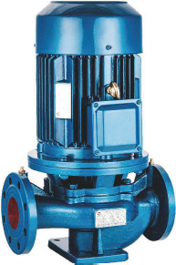 water pump is applied to supply clear water together with other liquid whose physical and chemical characters are equivalent to clear water, and it is appropriate for industrial and municipal water provide and sewerage, boosting water supply of high-rise developing, garden irrigation, boosting for fire fighting, long-distance delivery, heating and ventilating refrigeration circulation.
two.IRG,ISW horizontal and vertical hot water pump is suitable for: metallurgy, chemiacl market, weaving, paper producing.
three.IRG,ISW horizontal and vertical chemical pump is employed to supply liquid which is without sound particles, corrosive and comparable to water in viscosity.
4.ISGB vertical pipe centrifugal pump is often a type of solution which has new framework and sophisticated engineering, and is researched on the basis of ISG-type pump.
five.ISGB vertical pipe centrifugal pump delivers clear water together with other liquid whose physical and chemical characters are equivalent to clear water.(lf the media delivered is with particles, it need to be described when ordering so as to assemble sporting mechanic seal).
6.IHG-type vertical pipe chemical pump is employed to supply liquid that is with no strong particles, has corrosion and more powerful viscosity than water. It really is ideal for this kind of departments as petroleum, chemical marketplace, metallurgy, electrical electrical power, paper manufacture, food and pharmacy, synthetic fiber. Its operation temperature is among -20’C and 120’C.
slow rotary velocity centrifugal pump
ISWD. ISGD slow rotary velocity vertical centrifugal pump matches slow rotary velocity motor to the basis of ISGD-type vertical centrifugal pump, notably lowers the working noise, prolongs life span of very easily damaged elements. It is actually mostly utilized to freezing water, cooling water circulation of air-conditioning, terminal boosting, local or terminal boosting circulation of municipal heating method, local consistent voltage of city constructive fire-fighting technique, and setting of sorts of air-conditioning hot-water boiler.
The series no-jam dredge pump is created by means of intro ducing overseas productive vitality conservation no-jam dredge pump engineering and organizing the technological energy. Its trart parameters all reach or exceed the technological 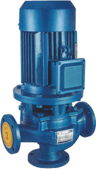 regular from the samekind item at home and abroad. It introduces one of a kind single-channel impeller, and motion seal can be a hard alloy mechanic seal fitting manufactured of two groups of unique supplies, motor is separated with oil chamber, it’s no?1am, wearies well, obtaining accurate model line, easy to utD?ze and sustain, has higher efficiency¡ê?saves energy notably, would be the newest solution from the identical variety in our country, and is deeply welcomed by its users. Several models and unique stricture forms from the pump is usually chosen.
The series no-jam dredge pump is ideal for delivering industrial and municipal sewage. Its beat characteris that it could deliver sewage with sound particles and fibre material. In addition to delivering sewage, it is also appropriate for dredge pump, pulp pump, 1?£¤rating washing condensat?¡ê??ycle pump, pump for irrigation and so on. It is actually widely utilized to this kind of events as mining, construction site, hospital, hotel, sewage therapy.
SPROCKET Functions
PLATE CENTER SPROCKETS
Sprockets are furnished in two fundamental types . . . Plate center and Spoked Arm. Plate centers are typically utilized on smaller sprockets whose size prohibits the usage of spoked arms and on drives and conveyors which are subjected to frequent shock loads. They are really also applied when the highest allowable chain pull is better than that which Spoked Arm Sprockets
can withstand.
SPOKED ARM SPROCKETS
Spoked arms are uncovered on big diameter sprockets. They are really made use of to reduce weight and facilitate handling.Lightening holes can also be utilized to reduce excess weight.
CHILLED RIM DISHED AND
FABRICATED DISHED
When making cast prockets, we use a unique chemistry of gray iron that enhances the skill with the with the iron to kind a hard “chilled” layer around the rim with the sprocket. All sprockets certainly are a normal class 30 gray iron. This applies to all areas on the sprocket which have been not chilled such because the hub and web parts. Surfaces possess a minimum brinell hardness of 400 more than the whole tooth pro?le.
Fabricated dished sprockets are created to order. Materials and hard-ness are customized for your requirements.
CHAIN SAVER SPROCKETS
Chain Saver sprockets give added lifestyle to chain since on the particular ?ange development on the rim. The chain side bars rest over the ?ange as chain wraps all over the sprocket, retaining the chain within the real pitch line and distributing wear more than a better get hold of region.
HUNTING TOOTH SPROCKETS
Hunting Tooth Sprockets final longer than ordinary sprockets and operate on this principle: Hunting Tooth Sprockets have an odd quantity of teeth and are half the pitch on the chain. So, each and every time the sprocket helps make a revolution, the chain links engage a brand new set of teeth, forward from the previously engaged set. Every tooth can make get in touch  with with all the chain only half as several instances since it would on a reg-ular sprocket, as a result doubling the life of your sprocket.
SEGMENTAL RIM SPROCKETS
Segmental Rim Sprockets are intended to eliminate pricey shut down time for the duration of installation and adjustment. They include a re-movable segmented rim in addition to a strong or split physique that are bolted collectively. To get more wear from this kind sprocket, after con-siderable use, the rim sections may possibly be only reversed, to ensure the chain can make get hold of using the opposite sides in the teeth. Bodies or complete sprockets might be replaced without having removing shaft or bear-ings, generating this sort of sprocket pretty desirable economically be-cause with the savings in labor and shut-down time.
Wide FLANGE SPROCKETS
These Sprockets are used in many industries this kind of since the lumber and paper industries as sprockets for the delivery finish of conveyors. The broad ?ange or side extension acts as a guard and aids hold materials from getting wasted because it comes off the finish of the conveyor.
TRACTION WHEELS
Traction wheels are available in the wide array of sizes and kinds to ?t most chains. They can be furnished in a plate-center design with op-tional lightening holes if expected. Traction wheels is often either sound, split or segmented construction.
Rugged building Style “MD” Buckets are most preferred for general goal elevators. Covering a broad choice of sizes from 4 to 20 inches lengthy, they’re utilised for ?ne and medium dimension elements such as coal, cement, pulp, grain, ear corn, etc. They’re  extensively used for heavy abrasive components this kind of as sand, gravel, and stone. Reinforced front lips give Style “MD” Buckets a long wearing digging edge. Uniform wall thickness and solid corner reinforcement make them stronger than steel buckets with the very same gauge.They’re smoothly surfaced and also have ends sloped inward at 6 degree angles to insure proper ?lling and clean discharge. Available in Malleable and Al-lied-Locke Promal.
Chain for which buckets can be found in-clude: Steel Bushed Roller, Steel Bushed, Combination, “H” Class Mill, 400 Class Pin-tle, and 700 Class Pintle. “MD” Buckets are utilized with G1, G6, K1, or K2 style attach-ments after they are available during the chain sort.
Capacities are for buckets ?lled to your line XX (see diagram). The useful working capability will vary using the loading disorders, angle of re-pose on the materials becoming handled, plus the incli-nation with the elevator.
Fashion “AC” ELEVATOR BUCKETS for managing cement, lime, and ?uffy products
Style “AC” Buckets present quickly, thorough discharge of cement, lime, and also other dry, ?uffy resources. Vent holes while in the bottom of every bucket release trapped air in ?lling and allow material to empty from bucket swiftly and wholly on discharge. Additionally to reinforcing lips, hooded backs reinforce “AC” Style Buckets. This characteristic permits closer bucket spacing and supplies 30% higher carrying capacity than other bucket variations from the same length. These sturdy buckets have an additional thickness of metal at put on factors for longer support. Obtainable in Al-lied-Locke Malleable and Promal.
Design “AC” Buckets usually are applied with heavy duty engineering chain this kind of as Bushed Steel Chain with K2 and K3 style attachments.
Capacities are for buckets ?lled to either line XX or YY (see diagram). The useful operat-ing capability will vary with loading problems, angle of repose of the materials being handled, as well as inclination in the elevator.
Elevator Buckets are made available in Styles ?¡ãMD?¡À Mill Duty and ?¡ãAC?¡À Additional Capacity.The ?¡ãMD?¡À Mill Duty Bucket replaces former Styles ?¡ãAA?¡À and ?¡ãAARB.?¡À
Design ?¡ãMD?¡À ELEVATOR BUCKETS
Type ?¡ãMD?¡À Elevator Buckets will be the most common buckets for general purpose elevators. They cover a broad range of sizes from 4 to twenty inches in length and are used for ?ne and medium size materi-als, this kind of as coal, cement, pulp, grain, and ear corn. They are really also extensively utilised for hefty abrasive materi-als such as sand, gravel, and stone. Reinforced front lips give buckets a long-wearing digging edge. Bucket walls have uniform thickness and sturdy corner rein-forcements. Seek the advice of our speci?cation tables for com-plete facts.
Available in Malleable and
Promal or in Fabricated Steel.
Design ?¡ãAC?¡À ELEVATOR BUCKETS
Style ?¡ãAC?¡À Elevator Buckets are additional ca-pacity buckets which offer rapidly, total discharge of cement, lime, together with other dry components.Vent holes while in the bottom of every bucket release trapped air on ?ll-ing and let materials to empty from bucket rapidly and entirely.The lips are reinforced along with the backs are hooded. These characteristics allow closer bucket spacing and offer  30% greater carrying capability than other bucket variations in the identical length. Buckets have more thickness of metal at wear factors. Seek advice from our speci?cation tables for total details.
Obtainable in Malleable and
Promal or in Fabricated Steel.
extended pitch 700 Class Pintle Chain of-fers greatest strength at minimal bodyweight. It is actually to-tally suited for sewage plant applications as well as other conveying and elevating uses. Sidebars have casted lugs to ?t.
T-head pins ?t snugly, getting rid of pin rotation and stopping the entrance of filth and grit in to the accu-rately cored pin holes. Closed bearing construction also aids to maintain the chain protected from pitch elonga-tion as a consequence of abrasive wear.
Riveted chain construction is suggested for sewage application, but both cottered or riveted con-struction is available on request. Stainless steel cot-ters might be furnished when speci?ed.
“F” attachments proven in the following pages and tables conform to business requirements. However, several specials are also offered. Get hold of for particulars.
700 Class Pintle Chain is furnished with carbon steel heat taken care of pins. These pins achieve optimum articulation given that they are man-ufactured to precise diameters which properly ?t the ac-curately cored holes in the chain links.
Brutaloy sprocket wheels are available.The curved sidebars on 700 Class Pintle Chain really are a function which enhances highest chain daily life when chain is run on Chain Saver Hunting Tooth Sprockets. A, F, K, and M Style 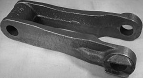 attachments are available. The “F” fashion attachments have massive face plates with bolt holes for safe mounting of wooden ?ights.
As drive chain, 700 Class Pintle backlinks are created to travel in the path of their barrel ends; as ele-vator and conveyor chain, they need to travel from the di-rection of their open ends. All 700 Class Chain is created to manufacturer’s standards and is in-terchangeable with other manufacturers’ chain.
400 Class Pintle Chain is actually a light-weight, moderately priced chain capable of han-dling normal loads at slow or intermediate speeds. It is proportionately cast for balance, strength and long, ef?cient support, and it is out there in riveted or cottered building. The head of every pin is notched to ?t the sidebar locking lug which keeps the pin from rotating once the chain is in use. Closed bearing construction makes 400 Class Pin-tle Chain helpful in conveying moderately gritty and abrasive materials.
Produced in Promal, that has a ten-sile power range from 7,800 to 28,600 pounds, 400 Class Pintle Chain is very carefully cored for pitch accuracy with smooth bearing sur-faces that reduce ?¡ãbreak-in?¡À wear creating pitch elongation.
400 Class Pintle Chain is available in the pitch selection of one.375 to three.075 inches having a total as-sortment of cast iron or fabricated steel steel sprockets.
A substantial assortment of attachments are available to manage a wide range of applications. Variations A and G attachments are supplied in ideal and left hand links.
As a drive chain, 400 Class Pintle is created to travel in the route from the barrel end on the hyperlinks; as an elevating or conveying chain, its route of travel should be toward the open ends in the hyperlinks.
All 400 Class Pintle Chain is manu-factured in accordance to manufacturer?¡¥s standards and is fully interchangeable with other manufac-turers?¡¥ chain.
A1  ATTACHMENT
NOTE: ?¡ãR?¡À and ?¡ãL?¡À suf?xes in Attachment Letters designate appropriate hand and left hand attachments.
A12 ATTACHMENT
NOTE: ?¡ãR?¡À and ?¡ãL?¡À suf?xes in Attachment Letters designate correct hand and left hand attachments.
TRANSFER CHAIN
is obtainable in two types: “H” Class Transfer Chain and Blend Transfer Chain. “H” Class Transfer Chain in-cludes people numbered H 78A, H 78B, H 130, H 131, and H 138. All “H” Class Transfer Chain is available only in riv-eted construction. “H” Class Transfer Chain numbered H 78A, H 130, and H 131 is created with peaked roofs. Chain numbered H 138 and H 78B has ?at roofs.
Blend Transfer Chain involves ![]() these numbered C55A, C55B, and C55C. It is actually obtainable only in riveted con-struction with peaked roofs.
these numbered C55A, C55B, and C55C. It is actually obtainable only in riveted con-struction with peaked roofs.
Both styles of Transfer Chain, referred to sometimes as “roof top” and “camelback” chain, are de-signed to carry heavily concentrated loads which include lum-ber, boxes, barrels, and crates.They can be normally intended for operation in troughs in two or far more parallel strands, with only the tops of your back links protruding.
All Transfer Chain is available in Promal. The tensile strengths of Transfer Chain range from 11,700 to 29,900 lbs.
Rivet pins furnished with “H” Class Trans-fer Chain are T-head pins which engage two head hold-ers, cast within the side bars of each link, to stop pin rotation and decrease dress in and elongation of pitch.
Transfer Chain is accessible in a pitch selection of one.631 to four.000 inches. Each Transfer Chain is manufactured in accordance to manufacturer’s stan-dards and might be interchanged with chain of other man-ufacturers, in which offered.
Cast Iron and Fabricated Steel sprockets are available for each pitch size.
“H” Class Mill Chain is definitely an ex-tremely sturdy, serviceable chain initially de-signed for hefty drives and transfer conveyor purposes in saw mills as well as the paper and pulp industry. “H” Class Chain has confirmed itself for innumerable other industrial applications also, specially for reasonable duty in abrasive atmospheres the place hefty, rugged chain is re-quired.
The sidebars of the “H” Class hyperlinks are rein-forced with wearing sneakers which strengthen and stiffen the backlinks when it truly is operated in troughs or in excess of ?oors and runways.
Pin holes are precision cored to assure accu-rate pitch sizes, which range from two.308 to four.000 inches. “H” Class Chain is obtainable in 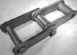 each riveted and cottered development. T-head pins engage two lugs cast around the links’ side-bars. This con?guration prohibits pin rotation throughout chain operation, getting rid of abrasive dress in and pitch elongation.
“H” Class Chain conforms to manufacturer’s standards and it is completely interchangeable with chains of other makers. “H” Class Chain is available in -Locke Promal with tensile ranges of 9,450 to 40,500 lbs.
“H” Class Chain could operate in two instructions. Like a drive chain, it travels during the route of the closed barrel; for elevator or conveyor applications, it really should travel towards the open ends of the back links.
Brutaloy or cast steel sprockets are available to accommodate each and every “H” Class pitch dimension. A broad assortment of attachments can be avail-able for varied chain applications.
Blend Chain is made use of extensively inside the cement, paper and pulp, quarrying, and mining industries for elevating and conveying a broad wide range of abrasive and non-abrasive materials. Additionally it is ?nding a lot of utilizes normally in-dustrial assembly conveyors. It really is not advisable for drive chain.
The construction of Mixture Chain might be both cottered or riveted. Cottered is typically consid-ered regular. Pins have ?at regions at their ends, which lock in to the appropriately punched sidebars, stopping pin ro-tation throughout chain operation. All pin holes are clean-cored for smooth bearing surfaces and therefore are dimensioned for appropriate pin clearance. Field dimensional specifications are rigidly maintained and this chain could possibly be interchanged with hyperlinks of other makers.
Pitch sizes vary from 1.631 to six.050 inches; tensile power assortment extends from twelve,150 to 67,500 pounds. All Combination block back links except C55 and C55L have elliptical barrels. This adds more metal where the sprocket to chain speak to causes most chain dress in.
MBP 132C has chambered barrels containing grease which lubricates pins, helps to prevent joint freezing, and pro-hibits entry of corrosive and abrasive materials in to the bar-rel core.
Attachments are available in many with the pitch sizes to get a wide variety of applications.
Blend links are symmetrical and may consequently be operated in both route of travel.
Brutaloy and cast steel sprockets are available for each pitch size.
COUPLER Backlinks FOR Combination CHAIN
Coupler back links are needed for joining chain wherever no take-up is obtainable. Every chain pitch size has a Promal cast off-set sidebar coupler website link readily 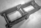 available for this function.
Engineering Class Drive Chain is intended for energy drives, building machinery 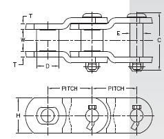 and conveyors. It operates beneath the most extreme situations at moderately large speeds. It is actually developed in accordance to ANSI or manufacturer’s requirements. It may be interchanged with common chains of other manufacturers, based on the dimension. You will find 4 fundamental designs.
Type one
Common offset design and style includes a roller, bushing, pin and typical offset sidebars
Style two
Special developed offset sidebars have a roller, bushing, pin and offset sidebars which can be specially formed to optimize articulation in which
Design 3
Steel bushed offset sidebar chain has a bushing, pin and offset sidebars. It does not have a roller
Fashion four
Straight sidebar drive chain has a roller, bushing, pin and straight sidebars
MXS and also other drive chain is available with pitch at present ranging from 1.500” to 7.000”. Regular greatest power ranges from twenty,000 to 600,000 lbs and functioning loads can be found from two,300 to 30,600 pounds. Drive chains are available in cottered development only. the pins are press fitted to the sidebars, avoiding pin rotation through chain operation. This also acheives maximum bearing surface amongst the pin as well as the sidebar. Offset drive chain should be run with all the closed finish first since the course of travel. Sprockets are available for all applications of our chain.
MSR Class Bushed Roller Steel Chain has higher power and lengthy dress in and is produced for hefty duty operation beneath significant disorders. Pins and bushings lock into specially created side-bars, assuring close pitch control and reaching as close to 100% bearing amongst the pin and side-bar as is possible. This configuration is commonly referred to as a “bushed roller”.
chain parts are manufactured from thoroughly chosen raw material, machined and heat handled employing precise and exacting specs; the elements are assembled with large precision for maximum performance and service.
This class of chain is available in a broad selection of pitch sizes. The encouraged operating load is conservatively stated in all sizes to help optimum functionality with prolonged life. This chain is made in accordance to manufacturers’ requirements and may very well be interchanged with common bushed roller chain of other producers. It is made available in four main variations:
Style 1 have oversized rollers. The outer diameter of the roller is larger compared to the sidebars
Design 2 have undersized rollers. The outer diameter on the roller could be the same height
or smaller sized than the sidebars
Type three have offset sidebars. The rollers could be over or undersized
Style four have tall sidebars that extend above the roller
Assorted attachments are presented  in a broad selection of MSR chain. Common elements, heat solutions and finishes may be personalized to fit your desires. Various grades of carbon, stainless and alloy steels can be found for most applications. We now have finish options this kind of as galvanizied, black oxide and various exclusive finishes.
MSR chain is accessible in riveted and cottered construction except as noted. Cottered building will probably be furnished unless of course riveted is requested, except 81X and MSR 303.
Sprockets are available for every one of the chains we manufacture.
SS Bushed Steel Chain is suitable for operating beneath very gritty or abrasive condi-tions. This chain is usually referred to as ?¡ãSteel Bushed?¡À or ?¡ãRollerless.?¡À Every component is machined and heat treated with all the result of power and put on, assuring optimum fit for the pins and bushings. Sidebars are developed to accommodate the ends in the pins which lock into position while in the sidebars and can not rotate in the course of operation.
The components used are thoroughly chosen. The pins are alloy steel that consist of nickel, chrome and molybdenum, which improves the chain life by means of its better fatigue resistance, improved abrasive resistance, and increased tensile strength at each higher and reduced temperatures. These elements lead  to a premium merchandise for conveyor and elevator support for gritty, abrasive, and fine particle materi-als such as ashes, crushed coal, soda ash, cement, crushed stone, and gravel.
? Pitch Array: two.609 – seven.000?¡À
? Average Ultimate Strength: 25,000 – 200,000 lbs
? Max. Rec. Operating Loads: two,750 – 27,500 lbs
Assorted attachments are made available. All of the cottered chain utilizes T-head cotters. Cottered construc-tion will probably be provided unless riveted is requested. SS Bushed Steel Chain is produced in ac-cordance with manufacturer?¡¥s specifications and may be interchanged with standard bushed steel chain of other suppliers. Sprockets are available in cast steel and fabricated when essential.
Sealed joint chain is accessible for much less servicing and higher wear resistance.
Roller chain would be the kind of chain most typically utilised for transmis-sion of mechanical energy on a lot of varieties of domestic, industrial and agricultural machinery, including conveyors, printing presses, vehicles, motorcycles, and bicycles.
Roller chain sizes are determined by 4 primary dimensions: pitch, within width from the roller hyperlink, roller diameter, and plate thickness. Pitch, the distance in inches in between centers of adjacent ?exing joints, types the proportional basis to the remaining dimensions. Chain dimension is  designated from the pitch dimension, and chain length is expressed when it comes to pitch, or in feet and inches.
ANSI Regular
Manufactured to ANSI/ASME Standard B29.1
Prestretched and produced with reliable rollers
Sizzling dipped lubrication soon after assembly to ensure right coverage
Solid Bushing Solid Roller
Dimensionally interchangeable with ANSI/ASME roller chain
Prestreched
Higher tensile strength than ANSI/ASME requirements
2-3X wear existence of normal chain
Hot dipped lubrication
Manufactured with strong bushings and strong rollers
For applications that demand less stretch and higher put on life than regular roller chain
Super Series
Dimensionally interchangeable with ANSI/ASME roller chain
Prestretched
Broad waist intended side plates for greater fatigue resistance
Produced with reliable bushings, solid rollers and as a result of hardened pins
Greater greatest allowable load than conventional roller chain
1.Ever-Power Vacuum Pumps Co.,Ltd.
Manufacturer of: Vacuum pumps of spiral slice type, Rotary Piston vacuum pumps, 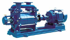 Roots Vacuum pumps, Cas-Cooling Roots Vacuum pumps, Rotary Vane Vacuum Pumps, Water ring Vacuum Pumps,Reciprocating vacuum pumps and Vacuum valves and verify values and also other associated vacuum goods and procedure.
HangZhou Ever-PowerVacuum Pumps Co.,Ltd. We have now the strongest advancement skill of vacuum pumps and vacuum equipments technologic.
Enterprise has superior style and design, Superior products, the largest vacuum pumps test center in China, also has currently established the strict Q/C systemas per ISO9001 standard. You’ll find total 25 big series of vacuum gear, Our merchandise are broadly utilized in departments of metallurgical, setting up supplies, petroleum, environmental, proteion, chemical, medicine, textiles, foods, aerospae, electronic, electrical power, nationwide defence industries and science analysis etc.
two.LIQUID (WATER) RING VACUUM PUMPS
Working principle and characteristics:
To the series SK, 2SK, YK and 2YK liquid ring vacuum pumps, multi-vane impeller is fixed ecceentrically in the pump casing. When the vanes rotate, the liquid during the casing kinds a liquid ring which is concentric using the pump casing under the centrifugal impact, the cubage in between liquid and vanes have a periodic alter, so the perform of pumping be performed. Liquid ring vacuum pumps are of the functions of minimal power consumption and reduced noise. They might be employed to pump water vapor, inflammable and explosive fuel at the same time as ordinary gases. With specific components applied for key components, they will also pump corrosive fuel. Appropriate actuating medium or often pumped medium may be chosen as actuating liquids, so the pumps can practically take care of all widely utilised for light, chemical, food, electric power and pharmaceutical industries, etc.
DUAL STAGE VACUUM PUMPS
110/220VAC Vacuum Pumps
Dual stage vacuum pumps operates on 110 VAC or 220VAC.Innovative dual-stage design pulls deep vacuum to 50 microns. Design and style of these one.five,three,5,eight,ten,12 CFM pump enhancements create within the performance-proven high-quality attributes. Whatever your vacuum pump needs, the proper pump will head to get the job done with you .
Dual stage design-second stage commences pumping at a reduced strain to pull a deeper greatest vacuum.
Preventing oil-returning design-prevents pump oil from being sucked into the system if a energy reduction takes place.
Gasoline ballast-speeds evacuation and keeps oil cleaner.
Large oil reservoir-lightweight and better dilute corrosive contaminants.
SINGLE STAGE VACUUM PUMPS
110/220VAC Vacuum Pumps
Single stage vacuum pumps operates on 110 VAC or 220VAC.  Picking the proper size pump from 1.five cfm to 9 cfm relies on your particular application. These pumps one particular engineered especially to help you do your task more rapidly and much better.
Substantial efficiency-CFM rated as ?°free air displacement.?±150 micron field rating.
Hefty duty substantial torque motor-assures cold weather staring.
Very low operating temperature-improve efficiency and vacuum.
Forced-feed lubrication design-help reduce operating temperature and far better Lubrication.
Working principle and capabilities:
The series HGL, HG pump can be a form of single-stage and single-cylinder rotary piston vacuum pump. It can be drastically enhanced series H rotary piston pump and includes 4 patents; its basic capabilities have a good improvement.
Rotary piston vacuum pump is a kind of vacuum manufacturing gear appropriate for pumping ordinary gases and condensable gases(when a gasoline ballast made use of). The pump need to be fitted with acceptable  add-ons if fuel is wealthy in oxygen, explosive, corrosive to ferrous metal, chemical reactive with vacuum pump oil.
Operation principle display in functioning principle graph: A rotary piston with slide valve across ecentric wheel driven by shaft within the housing. Piston pole can slide and swing freely in arch track. The whole pump chamber is divided into chamber A and chamber B by piston. When shaft rotates the volume of chamber A and chamber B are changed repetitively, to ensure that pumping objective may very well be achieved.
The series HGL, HG pump may be a backing pump when combined with one more higher vacuum pump as well as operate singly. It really is broadly used in vacuum smelting, vacuum drying, vacuum impregnation and higher vacuum simulation testing,and so on.
Working Principle and Attributes:
The series SYF roots vacuum pump is with overflow valve. The figure-of-eight rotors are counter-rotating at a continuous velocity inside the pump housing for suction and exhaust of gasoline. Two rotors are supported by two bearings and synchronized by a gear, which assures these two rotors in specified relative positions. They are really close to to one another and also to the housing with no real contacting, so lubrication is unnecessary during the operating housing. The meticulously balanced operating components and substantial precision bevel wheels ensue the pump be operated stably and constantly beneath the situation of high-pressure distinction. Dynamic seal component use our patent technologies and imported oil seals, the vibration quantity of shaft on the shaft seals is controlled to less than 0.02mm.
A gravity valve is put in concerning the suction and exhaust a part of the pump. The function in the gravity valve is as follows, when the pressure big difference between the suction and exhaust aspect is above the 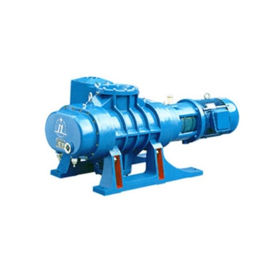 weight from the valve, the valve opens immediately, which makes the pressure big difference generally keep inside a fixed controllable value, the worth may be the allowable highest strain variation to make sure the pump work typically and so that actually, the roots vacuum pump with overflow valve is often a kind of overload self-protective pump.
Series SYF roots vacuum pump with overflow valve has substantially greater pace at reasonably lower inlet stress and it is actually possessed overload self-protective perform. As it is usually a pump of dry clearance seal construction, if a particular pumping velocity charge and an greatest vacuum have to be obtained, it’s needed to provide a reduce inlet strain for cutting down the back flow, hence, a pump have to be backed in use, roots vacuum pump really should be started off quickly immediately after its inlet pressure reaches a permissible value for economization.
It really is permit to select various types of pump because the backing pump for factual necessities, this kind of as oil seal pump and liquid ring vacuum pump. When pumping the gas containing big amount of vapor, the liquid ring vacuum pump is definitely the excellent backing pump.
Use scope
The single stage oil cycle vacuum pumps of spiral slice style of series SYF and double stage oil cycle vacuum pumps of spiral slice style in the series of 2SYF are necessary gear for abstracting the gas from obturational container to get vacuum. The double stage vacuum pumps of spiral slice kind on the serie of 2SYF made use of for abstracting to obtain vacuum again around the basis of single stage pumps. It could possibly make the technique achieve the highest point vacuum.
Capabilities
(1)The style of stopping oil-returning
The passage of gas admission is specially built to prevent the returning of pumps oil delivering the abstracted container and pipeline after the pumps stop operating.
(two)The layout of enviromental safety
The design and style of built-in gadget of mist getting rid of, and set oil-gas seperator over the vent, both deal with the pollution of oil all through the course of exhausting effectively.
(three) Aluminium alloy casing of electric machinery
The electrical machinery use aluminium alloy casing, it’s higher efficiency of heat emission, and be certain very long time regular operation continously, it also has improved appearance good quality.
(four) The design of integration
The electric machinery and pumps make use of the design of integration producing the products far more significant and sensible.
(five) Big starting up up moment
Our products patterns specially aiming at the enviroment of reduced temperation and electric stress. guaranteeing 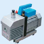 the machine commences usually at reduce temperatue of winter enviroment(?Y-5??) and reduced electrical strain(?Y180V).
YS Series three-Phase asynchronous Motors
Common introduction
YS series three-phase asynchronous motors are developed and produced according for the nationwide unified regular. It has the qualities of large efficiency, vitality conserving, reduced noise, very little vibration, extended services existence, easy upkeep and huge breakaway torque. It adopts class B insulation, IP 44 of safety degree and cooling mode of IC411. Rated voltage: 380V, Rated frequency: 50HZ. This series motors are broadly 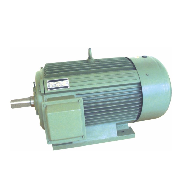 utilized to meals machineries, blower fans along with other machinery equipments.
YD Series multi-speed three-Phase asynchronous Motors
Standard introduction
This series motors are designed and manufactured under incorporating the advantages of the throughout the world counterparts, and therefore are in total conformity with worldwide typical of IEC. This series motors applied the process of changing the pole numbers to carry out velocity adjustment to ensure that they’ve got exceptional attributes like compact volume, lighter fat, reduced noise, very well starting overall performance, dependable operation, quick maintenance, and so on. The key technical indexes have reached the international technical regular.
The series motors are extensively used in different mechanical equipment which need to have stepped velocity adjustment; It enable the equipments to get compact structure, decrease noise and capacity of energy saving.
Simultaneously, multi-speed motors with particular specification could be created and produced in accordance towards the needs of consumer, this kind of as multi-speed three-phase asynchronous motor for YDT fans and pumps. Degree of safety: IP44, or IP54, or IP55; Rated voltage: 380V, rated frequency: 50HZ.
? YL series single phase dual-capacitor asynchronous motors are created and made in accordance with state standards, and also have out-standing development of commencing and operation, are of very low noise, compact imensions,light fat,straightforward servicing, etc.
? These motors could be widely utilized in air compressors,pumps,followers,refrigeration,health care instruments also as little machines,
and so on. in particular for event where only single
? phase electrical energy is 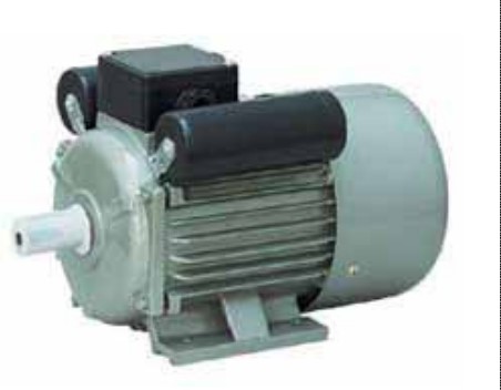 obtainable.
Protection variety: IP44 Insulation class: B
Rated voltage: 220V Cooling sort: IC0141
Duty kind: constant running Rated frequency: 50Hz
YC series heavy-duty single-phase motors are suitable for driving small machines and water pumps,especially for relatives or workshops the place only single-phase electrical supply can be found. Conforming to”IEC”designed with innovative procedures and made from best products, the motors have pleasant look and fantastic efficiency.
YC series motors are of IP44, completely enclosed and fan-cooled. Motor of rated output of 3HP and under are capacitor-started, when working below rated voltage, underneath 50Hz,includes a starting torque as higher as 3times the rated tone and underneath 60Hz,the torque can be two.75 occasions the rated one. Motors of 4HP and over are of capacitor start off and run. They have the benefits of high torque,regular working, reduced the mal rise, decrease noise and greater overload performan.
General introduction
Y2 series three-phase asynchronous motors, formulated with new approaches, are renewed and upgrading merchandise dependant on Y series motors.
Y2 series motors are in obdurate style and design and fan cooled sort, squirrel cage type and novel in style and good in look, compact construction, decrease noise, substantial efficiency, big torque, superb beginning effectiveness, effortless maintenance, and so on.. This series motors adopt F class insulation and designed against the insulation technique assessing system in accordance of worldwide practice.
Y2 series motors can be widely applied to various of driving equipments such as machine equipment, blowers, pumps, gearboxes, compressors, transporters, agricultural machines and so forth.
Working situations
Ambient temperature: 15 forty . Altitude: no larger than one thousand meters from sea level.
Rated voltage: 380V. Rated frequency: 50Hz,
Connection: Y connection 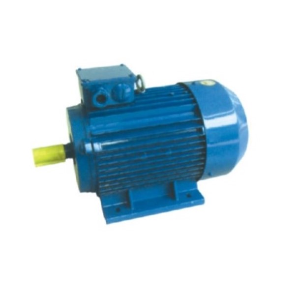 is adopted for motors below 3KW (3KW incorporated) and connection is adopted for other individuals over 4KW( 4KW integrated). Working ration: continuous doing work program (S1).
F class Insulation, the temperature rising of your stator winding examined at 80K(by resistance technique). Protection grade: on the main entire body is IP54, about the terminal box can reach IP55. Cooling strategy: Ic411.
The supporters are generally created of strengthen plastics other than that for frame sizes H315 as much as H355 are manufactured of aluminium-alloy or stamped with steel plate. Alt fan cowis are taken into shape by stret-ching with cold rolled steel plate to become high mec hanical power.
Hydraulic Auger Drives
AUGER DRIVE EARTH DRILL ATTACHMENT
TheEPG Auger Generate is large obligation constructed and constructed in a chopping edge facility. EPG partnered with expert CHINA to generate the very best Skid Steer Auger Push the North American market place has to offer you. The result is an aggressive Auger Drive,  offered in three designs, with sizeable torque per foot capabilities. Unnecessary to say, EPG is incredibly delighted. EPG purchases immediately from the resource and via an unique partnership with Skid Steer Options, is able to provide producer rates, without having the standard distributor mark-up.
Pick Product Choices Above
Decide on Auger Push Design
Decide on an Excavator Auger Cradle (Push Only alternative offered)
Select an Optional Auger Stump Planer (click on for information)
Pick an optional Auger Bit
Decide on a 2nd optional Auger Bit
The CHINA designed planetary gearbox provides an huge sum of torque and longevity to this Skid Steer Auger Generate. Competing companies still use shafts inserted from the entrance, with concerns of the shafts popping out when the retainer fails. EPG shafts are truly inserted from the again on a thrust plate that evenly distributes the fat. This provides you a distinctive mechanical advantage and provides more power at the little bit. It also guards towards the shaft from popping out and makes your operation significantly safer. EPG contains a lifetime guarantee from any shaft pullout. Additionally, the planetary gearbox is sealed with pre-set up lubrication, so there is no require for maintenance. All you have to do is connect your auger bit and do what you do best, work your compact equipment.
AUGER DRIVE EARTH DRILL ATTACHMENT
Functions
Intense, challenging operating,  and sturdy
Market foremost planetary gearbox design, maintenance cost-free
Life time ensure in opposition to shaft pullout
Hydraulic Flow Selection: seven-30 GPM (may differ by product)
Hoses included
Excavator Operating Fat
2500 Model: four,four hundred – 8,800 lbs. (2 – 4 T)
3500 Model: 5,500 -9,900 lbs. (two.5 – four.5 T)
4500 Product: 6,600 – eleven,000 lbs. (3 – 5 T)
Hydraulic Auger Drives
For a lot more agricultural gearbox info do not be reluctant to provide our pleasant staff a telephone call.
agricultural gearbox
Farmers perform tough each and every working day beneath demanding circumstances. and they rely on their gear to generate optimum productivity â all period extended. That is why top agricultural OEMs all around the globe  trust Weasler Engineering to produce wise gearbox options that improve the efficiency of their devices. From software overview and on-web site discipline screening to the latest design and style modeling and prototype analysis, Weaslerâs skilled engineering crew will work with you to build a gearbox answer for your gear. Weasler gearboxes are offered in a vast assortment of HP capacities, ratios and shaft configurations.
Customized Gearboxes
Weaslerâs personalized gearboxes are precision made and rigorously tested to meet up with the most demanding requirements. In the field, these hardworking solutions change the rotational power equipped by your equipment into the energy degree necessary by the particular software at the optimum pace and power required. Most kinds of farm machinery demand a personalized gearbox resolution to improve their functionality. Weasler engineers can perform with you to design and style and build a custom gearbox answer that exactly satisfies your demands and delivers a mechanical edge to boost torque and deliver constantly much better performance.
Bevel Gearboxes
Weasler gives bevel gearboxes in a extensive range of HP capacities. Pick from present ratios and shaft configurations or customize them to satisfy your certain software wants. Our engineers will function with you to entirely comprehend your specifications and dimensions the proper gearbox for your software. If your software needs a custom push resolution, our engineers will staff with you to design a bevel gearbox that meets your actual software to reduce tension and wear on your gear and prolong service lifestyle.
agricultural gearbox
 Parallel Shaft Gearboxes
Weasler Engineeringâs rugged parallel shaft gearboxes are designed to satisfy a extensive assortment of torque specifications in agriculture and other demanding markets. Decide on from current ratios and shaft configurations or personalize them to meet up with your application needs. Our engineers will work with you to understand your unique specifications and measurement the acceptable gearbox for your software. If your software calls for a personalized drive solution, our engineers will team with you to design a parallel shaft gearbox that fulfills your specific software to reduce stress and wear on your gear and extend service lifestyle.
agricultural gearbox
Get the important information you need about agricultural gearbox by visitng our internet site now.
China fluid coupling
KX is a consistent stuffed fluid coupling with a specific patented oil circuit made to begin up big inertia equipment driven by electric powered  motors
Oil or h2o constant fill
Compact and minimal starting torque design and style
High temperature Viton seals
ATEX design and style obtainable
Measurements from 15 to 29
Energy from a hundred to 1340hp
Inside fuse plug
Typical purposes:

Conveyors
Mills
Opened dri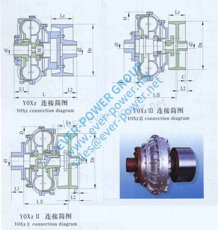 nking water fill for mine apps
China fluid coupling
BM-Collection Flexible Couplings
BM Equipment Couplings are developed for shaft-to-shaft set up, suitable for all engineering reasons in which a ongoing transmission of electrical power is required.
Positive aspects:
Virtually maintenance cost-free â âNO Grease Requiredâ
Shock and vibration damping
Compensation of misalignments
Swift and simple alter of versatile components
Are unsuccessful-safe and able of withstanding large overloads
17 various dimensions available with torque functionality exceeding 33100NM (24,414.fifty six lbs-ft)
China fluid coupling
Benefits:
Really smooth commence-ups /decreases motor overloads
Load sharing
Shock dampening
Jam load defense
Resilient
Self lubricating
Basic and user helpful
Set up and fail to remember
Applications:
Crushers
Grinders
Chippers
Conveyors
Mills
Pumps
Electric motor and inner combustion engines
Inline and facet load applications
China fluid coupling
Set Fill Fluid Coupling

We below at Kraft supply a entire line service for Transfluid products.
Countless numbers of buyers continue to decide on Transfluid products for the most varied and demanding purposes, being aware of that they can count on ever Powerâs complex providers division, where design, engineering and arranging authorities are usually on hand to assist resolve clientâs troubles as swiftly as achievable.
Transfluid Couplings
Transfluid has usually been a stage of reference in the globe  of industrial transmission equipment and the rule by which its opponents measure them selves. Get in touch with for more information, and to buy: +86-13083988828
Fluid couplings, variable speed drives, brakes, clutches, couplings and hydraulic transmissions constitute the main of the merchandise line, while ultra-modern technological innovation, cautious assortment of resources and meticulous assembly are the important ingredients in the recipe that has positioned those products at the forefront of the industry.
Low backlash right angle servo worm reducer
high precision worm gear is an ideal substitute for precision planetary gearbox,the equipment manufacturer can substantially reduce the price of using precision planetary gearbox
The designer’s ideal solution is to rotate 90 degrees to set up the servo motor drive systems
Worm shaft found in series could be driven by a single motor to attain synchronous productivity of multiple worm wheels. It’s been used in programmed polishing cellular phone shell and other equipments
Servo worm gear units have three types : 45 – 50 – 55 – 63 – 75 – 90 ,with dual business lead worm drive.Still left and best suited flank of worm shaft using different lead angle,leading to tooth thickness gradual transformation,To enable you to maneuver worm shaft and adjust backlash.
Low backlash Features :
— Worm gear gyration backlash can be adjusted to less than 1 arc.
— Reducer can be re-adjusted the gap after using .
— Input with coupling : reliable without backlash .
— Output using conical clamping ring couplings : reliable without backlash.
Applications :
Precision rotary motion
— Reducing the noise and vibration that’s caused by the load change and the change of cutting force.
— reducing the noise and impact that is caused by the corotation and reverse.
— By lowering worm abrasion.
— Increasing worm output response swiftness .
Precision Indexing device
— CNC machine, assembly line, cutting machine, transmitting lines, etc.
— Indexing device,accurate studying mechanism require accurate motion occasions .
Speed changing situations
— Reducing the noise and the impact that’s caused by speed change.
— Lowering the worm abrasion that’s due to speed changes.
Low rotation Make choice :
The following headings contain information on essential elements for selection and correct make use of gearbox.
For particular data on the gearbox spectrum,start to see the relevant chapters.
OUTPUT TORQUE
1、Rated output torque
Mn2 [Nm]
The torque that can be transmitted continuously through the output shaft, with the gear unit operated under a service factor fs = 1.
2、Required torque
Mr2 [Nm]
The torque demand based on application requirement. It is suggested to be equal to or less than torque Mn2 the gearbox under research is rated for.
3、Calculated torque
Mc2 [Nm]
Computational torque value to be utilized when choosing the gearbox. It is calculated considering the needed torque Mr2 and service point fs, as per the partnership here after:
POWER
1、Rated input power
Pn1 [kW]
The parameter are available in the gearbox rating charts and represents the KW which can be safely transmitted to the gearbox, based on input speed n1 and service factor fs= 1.
2、Rated output power
Pn2 [kW]
This value may be the power transmitted at gearbox output. it really is calculated with the next formulas:
EFFICIENCY
Efficiency is a good parameter which has a major impact on the sizing of certain applications, and basically is determined by gear pair designelements.
The mesh info table on page 9 shows dynamic efficiency (n1=1400)and static efficiency values.
Remember that these values are just achieved following the unit has been run found in and reaches the working temperature.
1、Dynamic efficiency
[ηd]
The dynamic efficiency may be the relationship of power delivered at output shaft P2 to power applied at input shaft P1:
2、Static efficiency
[ηs]
Efficiency obtained in start-up of the gearbox. Although that is generally certainly not significant element for helical gears, it might be instead critical when choosing worm gearmotors operating under intermittent duty.
SERVICE FACTOR [ fs ]
The service factor (fs ) depends upon the operating conditions the gearbox is subjected to the parameters that require to be taken under consideration to choose the most enough servies factor correctly comprise:
1. type of load of the operated equipment : A – B – C
2. length of daily working time: hours/day(△)
3. start-up rate of recurrence: starts/hour (*)
TYPE OF LOAD: A – uniform, fa≤0.3
B – 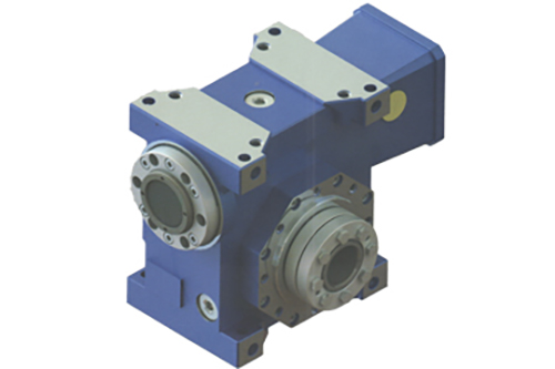 average shocks, fa≤3
C – hefty shocks, fa≤10
fa=Je/Jm
–Je(kgm2) point in time of the exterior inertia reduced at the travel shaft
–Jm(kgm2) minute of inertia of motor
–If fa>10 please contact our Technical Service
A -Screw feeders for light components, lovers, assembly lines, conveyor belts for light materials, tiny mixers, lifts, cleaning machines, fillers, control machines.
B -Winding equipment, woodworking machine feeders, goods lifts, balancers,threading equipment, medium mixers, conveyor belts for large materials,winches, sliding doors, fertilizer scrapers, packing devices, cement mixers, crane mechanisms, milling cutters, folding machines, equipment pumps.
C -Mixers for heavy products, shears, presses, centrifuges, rotating works with, winches and lifts for heavy materials, grinding lathes, natural stone mills, bucket elevators, drilling machines, hammer mills, cam presses, folding machines, turntables, tumbling barrels, vibrators, shredders.
series has a 90 degree insight via helical bevel equipment,and its giant tapered roller bearings also make it ideal for high radial and axial forces. PAR right angle reducer features an exceptionally short, light however rigid housing and full compatibility with standard motor adapters.PAR right position planetary gearbox combines the features of a compact right angle gearbox and those of a conventional planetary gearbox.Highest Accuracy, Highest Torque and Calm Operation are given by 100% optimized Helical Gearing.
With the compact structure but powerful design, PAR right angle planetary gearbox is ideal option for action control applications wherein the energy flow has to be redirected. So that it can support users to save the running price and enhance the transmission proficiency. The input flange measurements of PAR proper angle gearbox is open to be customized, therefore, it is appropriate for any brands of the servo motors, brushless DC motors and stepper motors.
1) High quality metal alloy die cast gearbox
2) High reliability worm gear and worm shaft
3) Less noises and lower temperature increase
4) Easy installation and linking, high efficiency
5) Power: 0.06-16 kW
6) Output torque: 1.8-1, 596 N. M
Output speed: 14-280rpm
If Double Gearbox, output quickness: 0.3-14rpm.
7) Ratio: 5-100
8) Inner packing: Carton; Outer packing: Plywood case.
9) Model amount: RV 030, 040, 050, 063, 075, 090, 110, 130, 150
1,Worm equipment gyration backlash could be adjusted to significantly less than 1 arc.
2,Reducer can be re-adjusted the gap after using.
3,Suggestions with coupling : reliable without backlash.
4,Output using conical clamping ring couplings : reliable without backlash.
5,Torque up to 7300Nm.
6,With servo coupling input.
7,Shrink disc(optional) for easy intergration.
8,Dual lead worm drive.
9,The ideal solution to lessen costs in servomotor application rather than bevel planetary gearheads.
Cycloidal pinwheel reducer is definitely a up-dated of brand-new type transmissing machine made with K-H-V less pearly whites engagement and the cycloidal pin wheel clenching mechanism, which are trusted in drive and reducing of textile and dying, foodstuff, mining and metallurgy, Oil and chemical cranes, Industry, task machinery etc and conveyors. various fields.
Features:
1. Gear is made from high durability low carbon alloy metal by carburizing and quenching. The hardness of tooth area can reach HRC58-62. CNC grinding technology is used for all good contact efficiency, gears and with substantial precision
2. high transmission performance: single stage over 96.5%; double stage over 93%; three stage over 90%;
3. stable operation and low noise;
4, compact structure, light weight, long service existence and high bearing potential;
5. easy to check, disassemble and assemble.
Operation specifications and precautions
1.High modularization design: various equip with various engine or other power suggestions conveniently.Same machine type may equip with numerous power motor. It really is easy to understand the combination and
junction between every machine type.
2.Transmission ratio: okay division, wide scope. The combined equipment type may form very large transmitting ratio, i.e. outcome very low rotary speed.
3.Form of unit installation: the positioning to be installed isn’t limited.
4.High strength, small: the box body is made of large strength cast iron. Gear and equipment shaft adapts the gas carbonization, quenching and fine grinding process, therefore the bearing potential of unitvolume is large.
5.Long life: Beneath the condition of correct type chosen (including choosing ideal operation parameters)normal procedure and maintenance, the life span of main elements of speed reducer (except sporting parts) shouldn’t be significantly less than 20000 hours. The wearing parts include lubricating bearing, oil and oil seal.
6.Low noise: because main elements of speed reducer are processed, assembled and tested critically,therefore the noise of speed reducer is going to be low;
7.Parallel axis -bevel wheel speed-down motor
cycloidal gear reducer
1. High velocity ratio and efficiency
Single stage transmission may reach to at least one 1:87 of speed-straight down ratio and the efficiency is certainly more than 90%. If work with multi-speed get the speed-down ratio is normally bigger.
2. Compact
Being adapted epicyclic transmitting basic principle, the input and outcome shaft are at same axis middle, it is compact.
3. Smooth and stable run and low noise
The cycloidal pinwheel has more meshed teeth, the overlapping coefficient id big and the device part is stable, the vibration and noise is limited anyway content.
1. Large deceleration ratio
A higher deceleration ratio of 1/30-1/320 can be acquired.The structure is easy, but it can realize high reduction ratio product.
2. Small gear clearance
The Travel, which meshes with ordinary gears and has minimal backlash, is essential to the controller business.
3. High precision
Multiple teeth are involved concurrently, and there are two gears engaged with 180 degree symmetry. Accordingly, the affect of tooth pitch error and cumulative tooth pitch error on the rotation accuracy is relatively average, making the positioning precision and rotation precision reach an extremely high level.
4. Less parts, easy installation
The three basic elements achieve a higher deceleration ratio, and they are all on a single axis, therefore the kit is simple to install and simple to shape.
5. Small in proportions and light in weight
Compared with 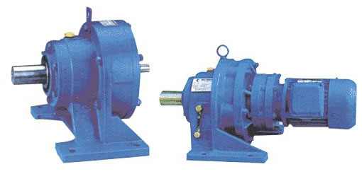 the prior gear device, the quantity is 1/3, the weight is 1/2, but can obtain the same torque capability and reduction ratio, obtaining small lightweight.
6 High torque capacity
Flexible wheel material USES particular steel with substantial fatigue strength.Not the same as ordinary transmission product, the quantity of teeth meshing accounts for in regards to 30% of the full total amount of teeth. Additionally, it is in contact with the surface, to ensure that the pressure borne by each equipment is reduced and large torque ability can be obtained.
7 High efficiency
The sliding of gear meshing parts is quite small, which reduces the power loss due to friction. Therefore, high reduction ratio can be achieved while maintaining high efficiency, and miniaturization of driving motor could be realized.
8. Low noise
The apparatus meshing cycle quickness is low, the transmission movements force balance, which means procedure is quiet, and the vibration is very small.
◆High speed ratio and large efficiency single-stage transmission can achieve a deceleration ratio of just one 1:87, and the efficiency is a lot more than 90%. If multi-stage transmission can be used, the deceleration ratio will become larger.
◆Because planetary transmission principle is adopted, the input shaft and end result shaft are on a single axis line, so that the machine unit can get the tiniest possible size.
◆The number of meshing teeth of cycloidal needle teeth with smooth running noise and low cycloidal noise is more, the overlap coefficient is much larger, and the mechanism of balancing machine parts creates the vibration and voice limited by a minimum.
◆Reliable use and very long service life because the primary parts are created from large carbon chromium steel, great strength is obtained by quenching (HRC58-62), and rolling friction is employed in a few transmission contacts, so the service life is prolonged.
Cycloid reducer is usually a cycloid needle teeth meshing planetary transmission principle drive models, is an ideal transmission has many advantages, versatile, and may be both negative and positive operation.
•Big ratio, and large efficiency Smooth operation,
• low noise The usage of reliable,
• extended life can reach 50000 hours
• Main parts high-carbon the Ming-steel after quenching treatment (HRC58-62),
• operation and connection with rolling friction, basically no wear, durable.
• Compact structure,
• small size Because the application of a planetary transmission, the type shaft and the output shaft on the same axis, making the model to get the smallest possible size.
• Reasonable design, easy maintenance, and breakdown easily install,
• minimal number of parts together with straightforward lubrication, cycloid reducer trusted by the user.
(1)Size above PL/PF120(including)high torque products adopt integral double wall planet pinion precision, improve the output strength and carrier.
(2).Hoop clamp coupling have five connection ways suitable for different application environments.
(3).Size over PL/PF120(including)precision and high power integral inner gear housing, processed in a single station,which eliminate the cumulative mistake and assembling mistake of split type.Get rid of casting process;adopt sizzling of forging process, that will reduce the blank material defects.
(4).The meshing gear adopt shaving procedure after carburizing and quenching,which much easier to make gear surface smooth and high accuracy,reduce the temperature rising caused by gear surface area gluing and friction.
This series worm-gear reducer was built after RV worm microreducer, that have a complete norm, wide speed for selection, and many mounting positions. Its effectiveness and mounting dime nsions conform the same types of foreign.
The combo of worm and gear has higher efficiency and wider speed range to single worm.
Designation of square shape, beautiful shape, compact structure, low noise and radiate heat efficiently.
Great sealing and adaptability.Its combo with T equipment reducer and MB/MBN variator may meet all types of speed requirement.
spur gears is an effective choice when you need to maximize the gearbox’s torque density or functioning life under larger loads. series inline type planetary gearbox provides an economical solution for clients who have limited budget. The square result flange assures the simpler mounting onto various devices, and huge viscosity & non-separated grease will be put on avoid any leakage. In addition, we can make the speed ratio up to 1000:1. is suitable for any brands of servo or stepper engine, such as for example SIEMENS, Mitsubiishi, Delta, Nema, Yaskawa, Panasonic, Schneider, Beckhoff, Kinco, Fanuc, etc. Besides, we’re able to provide input dimensions personalized service, thus, is all-rounder in the planetary gearbox market.
Gears, gear package ,worm wheel, worm equipment,plantery gearbox precision gearbox planetary gearbox
planetary gear reducer planetary reducer
Planetary gearboxes are used in huge precision applications in drive technology, when a high torque-to-volume ratio, great torsional stiffness and low backlash is required.
The main equipments are Hamai, marzak from Japan and so forth ,etc.
The advanced equipment to guarantee of high precision. Zero arcmin
to keep carefully the quality inadvanced
Components feature smooth, quiet, lightweight, compact helical equipment drives. These rugged systems, recognized as the QGH-52 Series give a choice of 3 backlash specifications: less than or equal to 15 arc min., significantly less than or equal to 10 arc min., or less than or add up to 3 arc min. Provided with sole or double stages, their effectiveness is definitely 95% or 92% respectively. The maximum input speed is 6000 rpm. The casing is aluminum with gears and output shafts created from 4135 alloy metal. Available gear ratios range from 3:1 to 25:1. The single level product weighs 0.55 kg (1.2 lb.) whereas the dual stage unit weighs 0.72 kg (1.6 lb.).
At the new eStore you may get immediate quotes, download 3D models,. ther power transmission solutions provided by include over 9,000 off-the-shelf timing belt pulleys, belts, belt and roller chain tensioners and additional pieces for prototypes and production applications.
Our gear box can produce according to your drawing or sample. Or you can let me know your detail utilization way and then we can suggest our ready items for your confirmation. Generally our outer case is casted. The gears happen to be specifically processed at processing center; The gears are made of high-quality alloy steel, are treated with surface hardening and gear floor if you request; And the key motor parts can be imported to meet your request. The whole gear box are excellent load-carrying low noise, ability, steady running and high efficiency. Our gear box have reached the advance foreign level, can replace the same sort of items imported. planetary reducer gearbox
value line gearbox spouse and children contains in-line, NEMA, and correct angle gearboxes offering exceptional torque rankings, bearing ability and low backlash for most of today’s servo and stepper applications.
The modular concept 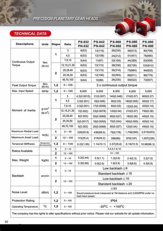 allows engineers to select from single or two stages of planetary gearing to create Hundres of standard ratios from 3:1 to 1000:1. A 1:1 right angle stage could be added for tight spaces.
Features include:
Ten frame sizes
Carburized and skived spur gearing
Steel housing and ring gear
Backlash only 5 arc-minutes
High capacity output bearings
One Piece Planetary carrier assure the strength
20,000 hour life
Grease filled for life and maintenance free
planetary reducer speed reducer worm reducer gearbox gear motor ac dc electric motor helical gear reducers planetary reducer
professional manufacturer reducer planet gear
servo motor helical gears box servo gear mind
hollow rotating reducer gears decrease gear boxes
Planetary gear planetary gear box gear electric motor gearbox
spur equipment reducer helical gear servo gear head
mini equipment reducer Hollow rotating reducer
reduction gear boxes servo motor helical gears box
series planetary gearbox use spiral bevel gears to understand the motor mounting with 90 level bending,it performs with low backlash and high rigidity,and also the mounting space is saved.
1. Space-Saving
Rectangular reducer use spiral bevel gears to make motor mounted in 90 degree bending, that is, save space.
2. Superior rigidity and torque
The rigidity and torque are heavily enhanced through the use of one-piece roller bearing.
3.Methods of connector and bush.
Can be installed on any motor all over the world.
4. No leakage of grease
Use large viscosity and non-separated grease in order to avoid the leakage.
5. Convenient Maintenance.
No need transformation the grease with the program period of reducer, install very much conveniently.
planetary gearbox is a type of high quality and low backlash proper angle gearbox, which makes the gearbox easily mounted to the motion system and give you a solution to solve the space problem. The inner development was created with spiral bevel gears which top features of better meshing substantial rigidity, low noise, even transmission and performance.
right angle gearbox isn’t only the ideal option for the movement control system with limited space, but likewise the best option for the transmission occasion that needs to 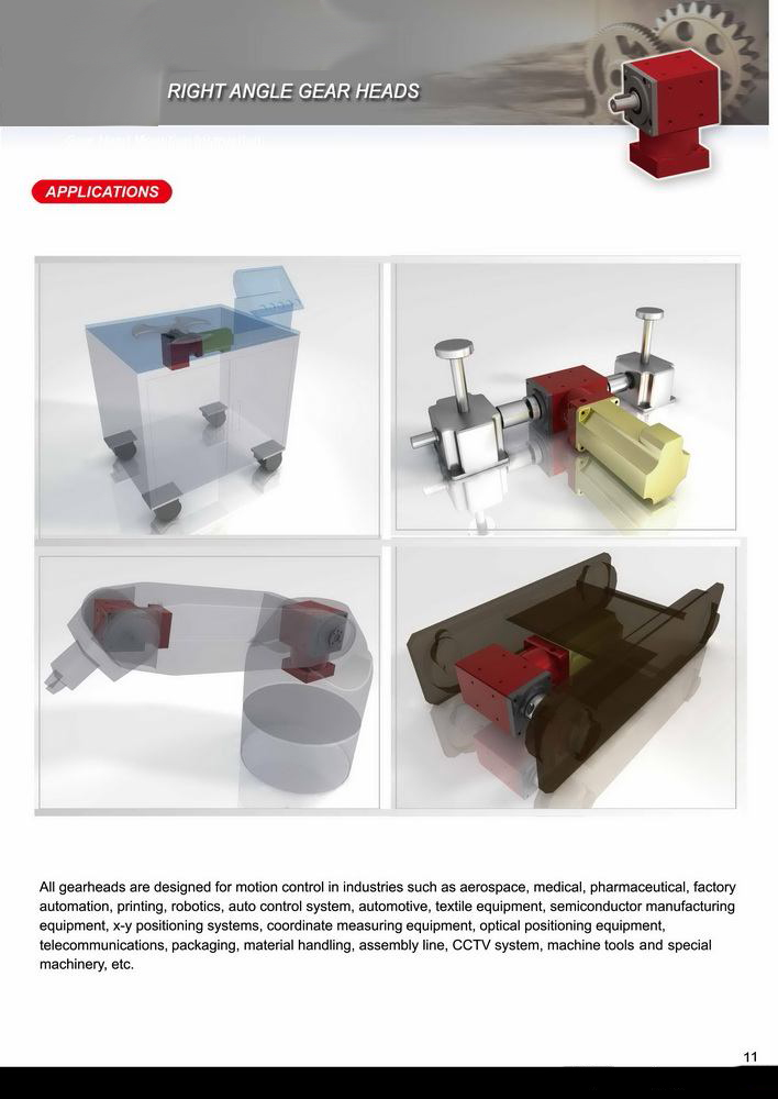 change the motion route. So it can support users to save lots of the running expense and improve the transmission efficiency.
1. Casing: Gray Cast Iron
2. Equipment Set: Spiral Bevel Equipment Pair
3. Input Configurations:
Single Keyed Input Shaft
Double Keyed Input Shafts
4. Output Configurations:
Single Keyed Output Shaft
Double Keyed Output Shafts
Features:
1. Sturdy cast iron gear field, hardened spiral bevel gears meshed in pairs, and solid bearings all contributing to reliable and optimal performance
2. A broad range of frame sizes, can be configured with numerous shaft configurations and equipment ratio
3. Low light vibration, large load ability and noise
4. Multiple mounting positions
5. Spiral bevel gears can be bidirectional rotation, easy operation at low or excessive speed
-Self-locking ability
-Can get driven directly by electric motor or other power or perhaps manual
-Can be customized according user’s demand
-Compact configuration, little size, lightweight
-Convenient installation, flexible operation
-High reliability and stability
-Long service life
-More connection form etc.
Screw is put on all areas for lifting or perhaps pulling, such as for example Aircraft maintenance program, Solar plate, machinery, metallurgy, water conservancy, medical treatment, chemical sector, hygienist etc and tradition.
Right-angle gearheads are flange-mounted gearheads that use worm gears and special helical gears. They allow motors to be installed at best suited angles to the axis of devices such as for example belt conveyors. They are available in hollow shaft RH and stable shaft RAA types and so are suitable for keeping equipment compact.
A right angle gearhead is commonly used when it’s essential to fit a servo motor into a tight space. The productivity shaft of the proper angle gearhead is at a 90-degree angle to the electric motor shaft. Therefore, the majority of the gearhead housing, and every one of the motor housing, is parallel to the side of the machine, providing a smaller machine envelope. Remember that some gearheads, such as for example worm gearheads, have an inherent correct angle design for the reason that drive axis of the worm (screw) reaches a 90 degree angle to the axis of the worm equipment.
Fig 1. A right-angle gearhead like this is generally used when it is necessary to fit a servo motor right into a tight space
Separate motors and gearheads
Most motion control systems that employ gearing use different motors and gearheads. This approach lets you pick the electric motor and gearhead best suited for the request, even when they result from different manufacturers. Typically, you can mount gearheads to virtually any servo engine. All that’s needed is is to mount the mating flanges alongside one another using common screws. This construction is more flexible than a gearmotor and it’s better to maintain. Gearheads degrade more quickly compared to the motor itself, therefore when a gearhead fails, you only have to replace it and not the motor.
Integrated gearmotors
That said, an integrated gearmotor is the best choice for certain applications. One good thing about this approach is the overall amount of the assembly can be an inch or more shorter than an assembly with a separate gearhead and motor.
System design is simpler too because you merely need a single speed and torque curve to determine if a good gearmotor provides the necessary performance to electric power your motion control program. This helps eliminate design errors.
And assembly is simpler as well. As the gearhead and electric motor are integrated, it’s impossible make the assembly faults discovered when mounting a gearhead to a motor.
Use in food processing
Integrated gearmotors work very well in severe environments such as for example found in the meals processing industry. Because gearmotor housings are likewise made with 300 grade stainless steel and must satisfy IP 69K standards for resistance to the ingress of substantial temperature-high pressure water, plant personnel can certainly clean down machinery without having to get worried about harming it. The look as well eliminates the seam between your electric motor and the gearhead, therefore there is absolutely no place for foodstuff to get caught.
Flange-face gearheads
A more recent trend is the utilization of flange-face gearheads. Instead of an result shaft, flange-deal with gearheads possess a rotating disk with screw holes on the end result. The device being driven mounts right to the flange. This arrangement eliminates the necessity for a flexible few and most of its associated challenges. Both gearheads and gearmotors can be found with a flange deal with.
Fig 2. To mount a gearhead to a servo motor, all that is required is to attach the mating flanges together using standard screws. Right here, a split collar mechanism on the input equipment secures it to the electric motor shaft.
There are numerous types of gearheads for use in a motion control system. Learning the attributes of each will help you make the best choice for different applications:
Selecting the right gearhead
There are various types of gearheads for use in a motion control system. Learning the attributes of every can help you make the best option for different applications:
Spur gears have pearly whites that go perpendicular to the face of the apparatus. They are compact, cost-effective, and capable of high equipment ratios. Negatives include they are noisy and susceptible to wear.
Worm gear drives are being used where it’s necessary to transmit power in a 90-degree angle and where great reductions are actually needed. Worm drives will be specific, run quietly, and want little maintenance. Disadvantages include they are comparatively low in proficiency and are nonreversible.
Planetary gear drives are so called because the gear arrangement somewhat resembles the solar program. A central equipment, called the sun equipment, drives planetary gears positioned around it. The planetary gears rotate the output shaft of the gearhead. Advantages include compact size, high productivity, low backlash, and a higher torque to weight ratio. Disadvantages include complex design and great bearing loads.
Harmonic gear drives include a wave generator, flexispine, and circular spine. Advantages include low weight, compact design, no backlash, large gear ratios, huge torque capacity, and coaxial type and output. A drawback is the gears are inclined to wear.
Cycloidal drives have an input shaft that drives an eccectric bearing which in turn drives a cycloidal disk. Cycloidal speed reducers can handle great ratios while remaining small in size. Cons include increased vibration, due to the cycloidal motion, that may cause don on the cycloidal disk’s teeth.
Fig 3. You merely need a single acceleration and torque curve to determine if an integrated gear motor like this has the necessary performance to electric power the motion-control system.
Three phase induction motors employ a simple construction composed of a stator protected with electromagnets, and a rotor made up of conductors shorted at each end, arranged as a “squirrel cage”. They work on the principle of induction in which a rotating Induction in Motor electro-magnetic field it made through the use of a three-phase current at the stators electromagnets. Therefore induces a current inside the rotor’s conductors, which in turns generates rotor’s magnetic field that attempts to follow stator’s magnetic field, pulling the rotor into rotation.
Great things about AC Induction Motors are:
Induction motors are basic and rugged in building. They are more robust and can operate in virtually any environmental condition
Induction motors are cheaper in expense because of simple rotor construction, absence of brushes, commutators, and slip rings
They are maintenance free motors unlike dc motors because of the absence of brushes, commutators and slip rings
Induction motors can be operated in polluted and explosive environments as they don’t have brushes that may cause sparks
AC Induction motors are Asynchronous Devices meaning that the rotor does not switch at the specific same speed since the stator’s rotating magnetic field. Some difference in the rotor and stator velocity is necessary to be able to develop the induction into the rotor. The difference between your two is named the slip. Slip must be kept in a optimal range in order for the motor to operate efficiently. Roboteq AC Induction controllers can be configured to operate in another of three modes:
Scallar (or Volts per Hertz): an Open up loop  mode in which a control causes a simultaneous, fixed-ratio Frequency and Voltage alter.
Controlled Slip: a Shut Loop speed where voltage and frequency are controlled in order to keep slip within a narrow range while running at a desired speed.
Field Oriented Control (Vector Drive): a Closed Loop Swiftness and Torque control that functions by optimizing the rotating field of the stator vs. this of the induced field in the rotor.
Observe this video from Learning Engineering for a visual illustration about how AC Induction Motors are constructed and work.
Three phase induction motors employ a simple construction composed of a stator protected with electromagnets, and a rotor composed of conductors shorted at each end, arranged as a “squirrel cage”. They focus on the principle of induction where a rotating electro-magnetic field it created by applying a three-phase current at the stators electromagnets. Therefore induces a current inside the rotor’s conductors, which in turns creates rotor’s magnetic field that attempts to check out stator’s magnetic field, pulling the rotor into rotation.
Great things about AC Induction Motors are:
Induction motors are simple and rugged in building. They are better quality and can operate in virtually any environmental condition
Induction motors are cheaper in expense due to simple rotor construction, absence of brushes, commutators, and slide rings
They are free of maintenance motors unlike dc motors due to the lack of brushes, Induction Motor commutators and slip rings
Induction motors could be operated in polluted and explosive conditions as they don’t have brushes which can cause sparks
AC Induction motors are Asynchronous Devices and therefore the rotor does not switch at the exact same speed as the stator’s rotating magnetic field. Some difference in the rotor and stator velocity is necessary to be able to create the induction into the rotor. The difference between the two is called the slip. Slip should be kept within an optimal range to ensure that the motor to operate efficiently. Roboteq AC Induction controllers could be configured to operate in one of three modes:
Scallar (or Volts per Hertz): an Open loop mode in which a control causes a simultaneous, fixed-ratio Frequency and Voltage modify.
Controlled Slip: a Shut Loop speed where voltage and frequency are managed in order to keep slip inside a narrow range while running at a desired speed.
Field Oriented Control (Vector Drive): a Closed Loop Acceleration and Torque control that functions by optimizing the rotating field of the stator vs. this of the induced field in the rotor.
Find this video from Learning Engineering for a visual illustration about how AC Induction Motors are constructed and function.
ep
July 9, 2020
This small DC motor runs off any electric battery or solar cell which range from 0.5-volts to 6-volts in fact it is our best all-purpose engine. It is ideal for experimenting with direct current (DC) electricity or creating motorized projects of your own design. It can also be utilized as a small DC generator.
This small DC motor rotates at about 1800 rpm at 2.0 volts. It really is smaller and quicker than our low acceleration DC motor.
Our small electric motors can be found in a variety of shapes and sizes for your convenience of choice. We have been producing high quality products since we first opened our doors in fact it is a custom that we make an effort to uphold long into the long term. Come and go through the excellent customer provider that people are guaranteed to provide! Visit our site or get in touch with our customer service department today!
FAQ
1 Q:What information should I tell you to confirm the product?
A: Model/Size, Transmission Ratio, Shaft directions & Order quantity.
2 Q: What if I don’t know which one I need?
A:Don’t worry, Send as much information as you can, our team will help you find the right one you are looking for.
3 Q:How long should I wait for the feedback after I send the enquiry?
A: Within 12 hours.
4 Q:What is your product warranty period?
A:We offer one year warranty since the vessel departure date left China.
5 Q:What industries are your gearboxes being used?
A:Our gearboxes are widely applied to light industry, food, beer & Small Electric in Motor beverage, chemistry, automatic storage equipment, paper, stage equipment, tobacco machinery etc.,
6,When you please an order, our team will confirm with you about color, package, method of payment and delivery, then a sales contract will be sent to you to confirm.
ep
July 8, 2020
Worm gears are used when huge equipment reductions are needed. It’s quite common for worm gears to have reductions of 20:1, and actually up to 300:1 or greater.
Many worm gears have an interesting property that no other gear established has: the worm can certainly turn the gear, but the gear cannot turn the worm. That is because the position on the worm is so shallow that when the apparatus attempts to spin it, the friction between your gear and the worm keeps the worm set up.
This worm gear feature is useful for machines such as conveyor systems, where the locking feature can act as a brake for the conveyor when the motor isn’t turning. One other very interesting utilization of worm gears is in the Torsen differential, which is utilized on some high-performance vehicles.
PRODUCT INTRODUCTION:
MAIN FEATURES:
1) Made of high quality aluminum alloy, light weight and non-rusting
2) Large output torque and high radiating efficiency 3) Smooth running and low noise, can work long time in dreadful condition
4) Good-looking appearance, durable service life and small volume
5) Suitable for omnibearing installation
MAIN MATERIALS:
1)housing: aluminium alloy ADC12(size 025-090); die cast iron HT200(size 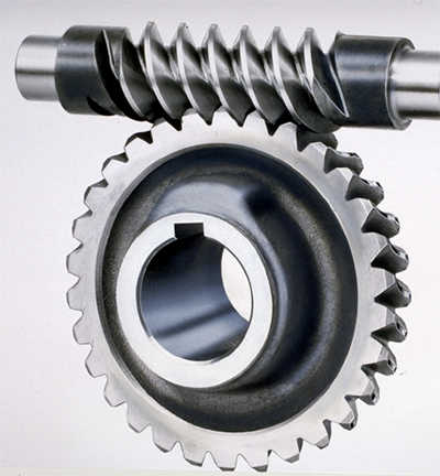 110-150);
2)Worm:20Cr, ZI Involute profile; carbonize&quencher heat treatment make gear surface hardness up to 56-62 HRC; After precision grinding, carburization layer’s thickness between 0.3-0.5mm.
3)Worm Wheel:wearable stannum alloy CuSn10-1
We started our business from 1995 and now we are the one of the leader manufacturer of power transmission products. It focuses mainly on Keyless Locking Devices, Timing Belt Pulleys, Roller Chains, Bearing, Jaw Couplings, Gears and other parts.
These products are produced in conformity with the International Standard and the standards adopted in industrialized countries (DIN ANSI BS JIS) with up to data equipment, advanced technology and perfect management system for quality control. It boasts a team with rich experience in this industry, focusing on global market. So the products are of good quality with competitive prices.
ep
July 8, 2020
fluid coupling
We give the fluid coupling and skills you need to have to keep your business in motion and make confident that practically nothing slows you down.
With a range of products customised to your software, our fluid couplings are made to give you full manage over your machine begin-ups, improving efficiency whilst saving time and income in maintenance and downtime.
With a powerful perception in innovation, we use more than 50 years of knowledge and expertise to develop and source the greatest couplings offered for your company.
At KTR, we are a major maker of higher-quality electrical power transmission technology, braking and cooling techniques, and hydraulic components.
Each model has its benefit. The internal wheel push requires less electrical power in the course of the st art-up of the engine and has standardisation of bores for uniform shafts of the electric powered motors. With a hold off chamber, the interior wheel generate also has a slow-start up as the oil is sucked into the workspace. Alternatively, the outer wheel drive has great warmth dissipation which makes it perfect for apps with frequent or long beginning processes. The outer wheel also has an simpler oil setting, which implies that it can be turned out without relocating the push or the driven machine.
Do your research study … you’ll discover people are absolutely satisfied with Auger Drive.
ep
July 8, 2020
Two important principles in gearing are pitch surface and pitch position. The pitch surface area of a gear is the imaginary toothless surface that you would possess by averaging out the peaks and valleys of the average person teeth. The pitch surface area of a typical gear is the form of a cylinder. The pitch angle of a gear is the angle between your face of the pitch surface and the axis.
The most familiar types of bevel gears have pitch angles of significantly less than 90 degrees and therefore are cone-shaped. This kind of bevel gear is named external because the gear teeth stage outward. The pitch areas of meshed exterior bevel gears are coaxial with the gear shafts; the apexes of the two areas are at the point of intersection of the shaft axes.
Bevel gears that have pitch angles in excess of ninety degrees have teeth that time inward and are called beval gearbox internal bevel gears.
Bevel gears which have pitch angles of exactly 90 degrees possess teeth that time outward parallel with the axis and resemble the factors on a crown. That’s why this kind of bevel gear is called a crown gear.
Mitre gears are mating bevel gears with equivalent numbers of teeth and with axes at right angles.
Skew bevel gears are those for which 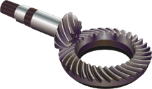 the corresponding crown gear has the teeth that are straight and oblique.
ep
July 6, 2020
This small DC motor runs off any electric battery or solar cell  ranging from 0.5-volts to 6-volts and it is our best all-purpose engine. It really is ideal for experimenting with immediate current (DC) electrical power or creating motorized projects of your design. It may also be used as a little DC generator.
This small DC motor rotates at about 1800 rpm at 2.0 volts. It is smaller and quicker than our low quickness DC motor.
Our small electric motors can be found in a variety of shapes and sizes for your capability of choice. We have been producing high quality products since we initial Small Electric Motor opened our doors and it is a custom that we strive to uphold long into the long term. Come and go through the excellent customer support that people are guaranteed to provide! Visit our site or get in touch with our customer support department today!
ep
July 2, 2020
rotary cutter gearbox
Notice:
If you might be rapid, you’ll recognize that some gearboxes demonstrate up in much more than a single “Horsepower Score”. We did our very best to set things where people might assume to uncover them. Some gearboxes failed to suit into ONLY one particular group. Now you know why.
The easiest way to uncover your assembly amount is to carefully (go through: delicately) get rid of the manufacturer’s paint from the ID tag on your gearbox and read the stamping off of the tag. If you are unable to find the tag or if it blew absent in  very last year’s storm, give us a contact or use the fall-down menus to “build-out” your gearbox on our site.
The greatest way to find your actual Omni Equipment replacement gearbox is to use the six-digit assembly number stamped on every single Omni Equipment gearbox.
These codes nearly constantly start with “25” followed by four far more digits. For example: the most frequent five-6 foot cutter gearbox is the 250001.
This code phone calls out shafts, ratios, equipment kind… every little thing.
How do we know? Straightforward. They use the exact same gearbox assembly amount.
An assembly of meshed gears comprising a central or sun gear, a coaxial internal or ring equipment, and a number of intermediate pinions supported upon a revolving carrier. Sometimes the word planetary gear train is utilized broadly as a synonym for epicyclic equipment teach, or narrowly to point that the ring equipment is the set member. In a simple planetary gear teach the pinions mesh at the same time with both coaxial gears (see illustration). With the central gear set, a pinion rotates about any of it as a planet rotates about its sun, and the gears are named accordingly: the central gear may be the sun, and the pinions are the planets.
This is a compact, ‘single’ stage planetary gearset where the output comes from another ring gear varying a few teeth from the primary.
With the initial model of 18 sun teeth, 60 band teeth, and 3 planets, this resulted in a ‘single’ stage gear reduction of -82.33:1.
A normal planetary gearset of this size would have a reduction ratio of 4.33:1.
That is a whole lot of torque in a small package.
At Nominal Voltage
Voltage (Nominal) 12V
Voltage Range (Recommended) 3V – 12V
Speed (No Load)* 52 rpm
Current (No Load)* 0.21A
Current (Stall)* 4.9A
Torque (Stall)* 291.6 oz-in (21 kgf-cm)
Gear Ratio 231:1
Gear Material Metal
Gearbox Style Planetary
Motor Type DC
Output Shaft Diameter 4mm (0.1575”)
Output Shaft Style D-shaft
Output Shaft Support Dual Ball Bearing
Electrical Connection Man Spade Terminal
Operating Temperature -10 ~ +60°C
Installation Screw Size M2 x 0.4mm
Product Weight 100g (3.53oz)
In an epicyclic or planetary gear train, several spur gears distributed evenly around the circumference operate between a gear with internal teeth and a gear with exterior teeth on a concentric orbit. The circulation of the spur equipment takes place in analogy to the orbiting of the planets in the solar system. This is how planetary gears acquired their name.
The parts of a planetary gear train could be split into four main constituents.
The housing with integrated internal teeth is known as a ring gear. In the majority of cases the housing is fixed. The traveling sun pinion is in the center of the ring gear, and is coaxially arranged in relation to the output. The sun pinion is usually mounted on a clamping system to be able to provide the Planetary Gear Transmission mechanical connection to the electric motor shaft. During operation, the planetary gears, which are installed on a planetary carrier, roll between the sunlight pinion and the ring equipment. The planetary carrier also represents the output shaft of the gearbox.
The sole purpose of the planetary gears is to transfer the required torque. The number of teeth has no effect on the tranny ratio of the gearbox. The number of planets can also vary. As the amount of planetary gears boosts, the distribution of the strain increases and therefore the torque that can be transmitted. Raising the amount of tooth engagements also decreases the rolling power. Since only part of the total result needs to be transmitted as rolling power, a planetary gear is extremely efficient. The benefit of a planetary equipment compared to an individual spur gear lies in this load distribution. It is therefore possible to transmit high torques wit
h high efficiency with a compact design using planetary gears.
Provided that the ring gear has a constant size, different ratios could be realized by varying the number of teeth of the sun gear and the number of teeth of the planetary gears. The smaller the sun equipment, the greater the ratio. Technically, a meaningful ratio range for a planetary stage can be approx. 3:1 to 10:1, because the planetary gears and the sun gear are extremely small above and below these ratios. Higher ratios can be acquired by connecting a number of planetary stages in series in the same ring gear. In cases like this, we speak of multi-stage gearboxes.
With planetary gearboxes the speeds and torques can be overlaid by having a ring gear that is not set but is driven in virtually any direction of rotation. It is also possible to repair the drive shaft to be able to grab the torque via the ring gear. Planetary gearboxes have grown to be extremely important in many areas of mechanical engineering.
They have become particularly more developed in areas where high output levels and fast speeds must be transmitted with favorable mass inertia ratio adaptation. High transmitting ratios may also easily be performed with planetary gearboxes. Because of the positive properties and small design, the gearboxes have many potential uses in industrial applications.
The advantages of planetary gearboxes:
Coaxial arrangement of input shaft and output shaft
Load distribution to many planetary gears
High efficiency because of low rolling power
Almost unlimited transmission ratio options due to combination of several planet stages
Ideal as planetary switching gear because of fixing this or that area of the gearbox
Chance for use as overriding gearbox
Favorable volume output
Suitability for an array of applications
In an epicyclic or planetary gear train, several spur gears distributed evenly around the circumference run between a gear with internal teeth and a gear with exterior teeth on a concentric orbit. The circulation of the spur equipment occurs in analogy to the orbiting of the planets in the solar program. This is one way planetary gears acquired their name.
The components of a planetary gear train can be split into four main constituents.
The housing with integrated internal teeth is known as a ring gear. In the majority of cases the casing is fixed. The traveling sun pinion can be in the center of the ring equipment, and is coaxially organized in relation to the output. Sunlight pinion is usually mounted on a clamping system in order to offer the mechanical link with the engine shaft. During procedure, the planetary gears, which are installed on a planetary carrier, roll between your sunlight pinion and the ring gear. The planetary carrier also represents the result shaft of the gearbox.
The sole purpose of the planetary gears is to transfer the required torque. The amount of teeth has no effect on the tranny ratio of the gearbox. The number of planets can also vary. As the amount of planetary gears boosts, the distribution of the strain increases and therefore the torque which can be transmitted. Raising the number of tooth engagements also decreases the rolling power. Since only part of the total output has to be transmitted as rolling power, a planetary gear is incredibly efficient. The advantage of a planetary gear compared to a single spur gear is based on this load distribution. It is therefore possible to transmit high torques wit
h high efficiency with a compact style using planetary gears.
Provided that the ring gear has a constant size, different ratios can be realized by various the amount of teeth of sunlight gear and the amount of the teeth of the planetary gears. Small the sun equipment, the higher the ratio. Technically, a meaningful ratio range for a planetary stage is usually approx. 3:1 to 10:1, because the planetary gears and sunlight gear are extremely little above and below these ratios. Higher ratios can be acquired by connecting many planetary levels in series in the same ring gear. In this instance, we speak of multi-stage gearboxes.
With planetary gearboxes the speeds and torques can be overlaid by having a band gear that’s not fixed but is driven in virtually any direction of rotation. Additionally it is possible to fix the drive shaft in order to grab the torque via the band equipment. Planetary gearboxes have become extremely important in lots of areas of mechanical engineering.
They have become particularly more developed in areas where high output levels and fast speeds should be transmitted with favorable mass inertia ratio adaptation. High transmitting ratios may also easily be performed with planetary gearboxes. Because of their positive properties and small design, the gearboxes possess many potential uses in commercial applications.
The advantages of planetary gearboxes:
Coaxial arrangement of input shaft and output shaft
Load distribution to several planetary gears
High efficiency because of low rolling power
Nearly unlimited transmission ratio options due to combination of several planet stages
Suitable as planetary switching gear due to fixing this or that portion of the gearbox
Possibility of use as overriding gearbox
Favorable volume output
Suitability for an array of applications
Epicyclic gearbox is an automatic type gearbox in which parallel shafts and gears set up from manual equipment box are replaced with more compact and more reliable sun and planetary kind of gears arrangement and also the manual clutch from manual power train can be replaced with hydro coupled clutch or torque convertor which in turn made the transmission automatic.
The idea of epicyclic gear box is taken from the solar system which is considered to the perfect arrangement of objects.
The epicyclic gearbox usually includes the P N R D S (Parking, Neutral, Invert, Drive, Sport) modes which is obtained by fixing of sun and planetary gears based on the require of the drive.
Within an epicyclic or planetary gear train, several spur gears distributed evenly around the circumference run between a gear with internal teeth and a gear with external teeth on a concentric orbit. The circulation of the spur gear takes place in analogy to the orbiting of the planets in the solar program. This is one way planetary gears obtained their name.
The parts of a planetary gear train can be divided into four main constituents.
The housing with integrated internal teeth is actually a ring gear. In the majority of cases the housing is fixed. The traveling sun pinion is usually in the center of the ring gear, and is coaxially organized with regards to the output. The sun pinion is usually attached to a clamping system to be able to provide the mechanical link with the motor shaft. During procedure, the planetary gears, which are mounted on a planetary carrier, roll between your sun pinion and the ring gear. The planetary carrier also represents the output shaft of the gearbox.
The sole purpose of the planetary gears is to transfer the mandatory torque. The number of teeth has no effect on the tranny ratio of the gearbox. The amount of planets may also vary. As the number of planetary gears raises, the distribution of the strain increases and then the torque which can be transmitted. Increasing the number of tooth engagements also decreases the rolling power. Since just section of the total output needs to be transmitted as rolling power, a planetary equipment is incredibly efficient. The advantage of a planetary gear compared to a single spur gear lies in this load distribution. It is therefore possible to transmit high torques wit
h high efficiency with a compact design using planetary gears.
So long as the ring gear has a constant size, different ratios can be realized by varying the number of teeth of the sun gear and the amount of teeth of the planetary gears. Small the sun equipment, the greater the ratio. Technically, a meaningful ratio range for a planetary stage is approx. 3:1 to 10:1, because the planetary gears and the sun gear are extremely small above and below these ratios. Higher ratios can be obtained by connecting many planetary phases in series in the same ring gear. In this case, we speak of multi-stage gearboxes.
With planetary gearboxes the speeds and torques could be overlaid by having a band gear that is not set but is driven in virtually any direction of rotation. Additionally it is possible to fix the drive shaft in order to grab the torque via the ring gear. Planetary gearboxes have become extremely important in lots of areas of mechanical engineering.
They have grown to be particularly more developed in areas where high output levels and fast speeds should be transmitted with favorable mass inertia ratio adaptation. High transmitting ratios may also easily be achieved with planetary gearboxes. Because of their positive properties and compact design, the gearboxes possess many potential uses in commercial applications.
The advantages of planetary gearboxes:
Coaxial arrangement of input shaft and output shaft
Load distribution to several planetary gears
High efficiency due to low rolling power
Nearly unlimited transmission ratio options because of mixture of several planet stages
Ideal as planetary switching gear due to fixing this or that section of the gearbox
Possibility of use as overriding gearbox
Favorable volume output
In a planetary gearbox, many teeth are involved at once, that allows high speed decrease to be performed with fairly small gears and lower inertia reflected back to the motor. Having multiple teeth discuss the load also enables planetary gears to transmit high levels of torque. The combination of compact size, huge speed decrease and high torque tranny makes planetary gearboxes a popular choice for space-constrained applications.
But planetary gearboxes perform involve some disadvantages. Their complexity in design and manufacturing can make them a far more expensive remedy than various other gearbox types. And precision production is really important for these gearboxes. If one planetary equipment is put closer to sunlight gear compared to the others, imbalances in the planetary gears can occur, leading to premature wear and failing. Also, the compact footprint of planetary gears makes warmth dissipation more difficult, therefore applications that run at high speed or experience continuous operation may require cooling.
When utilizing a “standard” (i.electronic. inline) planetary gearbox, the motor and the powered equipment must be inline with one another, although manufacturers provide right-angle designs that incorporate other gear sets (frequently bevel gears with helical teeth) to provide an offset between the input and output.
Input power (max)27 kW (36 hp)
Input speed (max)2800 rpm2
Output torque (intermittent)12,880 Nm(9,500 lb-ft)
Output torque (continuous)8,135 Nm (6,000 lb-ft)
1 Actual ratio is dependent on the drive configuration.
2 Max input speed related to ratio and max result speed
3 Max radial load placed at optimum load position
4 Weight varies with configuration and ratio selected
5 Requires tapered roller planet bearings (not available with all ratios)
Approximate dry weight100 -181 kg (220 – 400 lb)4
Radial load (max)14,287kg (31,500 lb)3
Drive typeSpeed reducer
Hydraulic engine input SAE C or D hydraulic
A planetary transmission program (or Epicyclic system as it is also known), consists normally of a centrally pivoted sun gear, a ring equipment and several planet gears which rotate between these.
This assembly concept explains the term planetary transmission, as the planet gears rotate around the sun gear as in the astronomical sense the planets rotate around our sun.
The benefit of a planetary transmission depends upon load distribution over multiple planet gears. It really is thereby feasible to transfer high torques employing a compact design.
Gear assembly 1 and equipment assembly 2 of the Ever-Power 500/14 possess two selectable sunlight gears. The first gear stage of the stepped world gears engages with sunlight gear #1. The next equipment step engages with sunlight gear #2. With sun gear one or two 2 coupled to the axle,or the coupling of sun gear 1 with the band gear, three ratio variants are achievable with each gear assembly.
Direct Gear 1:1
Example Gear Assy (1) and (2)
With direct equipment selected in equipment assy (1) or (2), the sun gear 1 is coupled with the ring equipment in gear assy (1) or gear assy (2) respectively. Sunlight gear 1 and band gear then rotate with each other at the same quickness. The stepped planet gears do not unroll. Hence the apparatus ratio is 1:1.
Gear assy (3) aquires direct gear predicated on the same principle. Sunlight gear 3 and band gear 3 are directly coupled.
Many “gears” are utilized for automobiles, however they are also utilized for many other machines. The most typical one may be the “transmitting” that conveys the power of engine to tires. There are broadly two roles the transmission of an automobile plays : one is definitely to decelerate the high rotation swiftness emitted by the engine to transmit to tires; the other is to change the reduction ratio in accordance with the acceleration / deceleration or traveling speed of a car.
The rotation speed of an automobile’s engine in the overall state of driving amounts to 1 1,000 – 4,000 rotations each and every minute (17 – 67 per second). Since it is not possible to rotate tires with the same rotation acceleration to run, it is necessary to lower the rotation speed utilizing the ratio of the number of gear teeth. Such a role is named deceleration; the ratio of the rotation quickness of engine and that of tires is named the reduction ratio.
Then, exactly why is it necessary to alter the reduction ratio in accordance with the acceleration / deceleration or driving speed ? This is because substances need a large force to start moving however they usually do not require this kind of a huge force to keep moving once they have started to move. Automobile can be cited as an example. An engine, however, by its nature can’t so finely modify its output. Consequently, one adjusts its output by changing the reduction ratio employing a transmission.
The transmission of motive power through gears quite definitely resembles the principle of leverage (a lever). The ratio of the number of tooth of gears meshing with one another can be deemed as the ratio of the space of levers’ arms. That is, if the decrease ratio is large and the rotation acceleration as output is low in comparison to that as input, the power output by transmission (torque) will be huge; if the rotation velocity as output is not so lower in comparison compared to that as insight, on the other hand, the power output by tranny (torque) will be little. Thus, to improve the reduction ratio utilizing transmission is much comparable to the basic principle of moving things.
Then, how does a tranny alter the reduction ratio ? The answer is based on the system called a planetary gear mechanism.
A planetary gear mechanism is a gear mechanism consisting of 4 components, namely, sun gear A, several planet gears B, internal gear C and carrier D that connects planet gears as observed in the graph below. It has a very complex structure rendering its design or production most difficult; it can realize the high reduction ratio through gears, nevertheless, it is a mechanism suitable for a reduction system that requires both small size and high performance such as for example transmission for automobiles.
The planetary speed reducer & gearbox is a kind of transmission mechanism. It utilizes the velocity transducer of the gearbox to reduce the turnover amount of the engine to the required one and obtain a big torque. How will a planetary gearbox work? We are able to learn more about it from the framework.
The primary transmission structure of the planetary gearbox is planet gears, sun gear and band gear. The ring gear is situated in close get in touch with with the internal gearbox case. The sun gear driven by the exterior power lies in the center of the ring equipment. Between your sun gear and band gear, there exists a planetary equipment set consisting of three gears equally built-up at the planet carrier, which is certainly floating among them counting on the support of the output shaft, ring gear and sun gear. When sunlight equipment can be actuated by the insight power, the planet gears will be driven to rotate and then revolve around the guts combined with the orbit of the band equipment. The rotation of the earth gears drives the output shaft connected with the carrier to output the power.
Planetary speed reducer applications
Planetary speed reducers & gearboxes have a whole lot of advantages, like small size, light weight, high load capability, lengthy service life, high reliability, low noise, huge output torque, wide variety of speed ratio, high efficiency and so on. Besides, the planetary quickness reducers gearboxes in Ever-Power are created for square flange, which are easy and practical for installation and ideal for AC/DC servo motors, stepper motors, hydraulic motors etc.
Because of these advantages, planetary gearboxes can be applied to the lifting transportation, engineering machinery, metallurgy, mining, petrochemicals, building machinery, light and textile sector, medical equipment, device and gauge, car, ships, weapons, aerospace and other commercial sectors.
The primary reason to use a gearhead is that it makes it possible to regulate a large load inertia with a comparatively small motor inertia. Without the gearhead, acceleration or velocity control of the load would require that the engine torque, and thus current, would need to be as many times higher as the decrease ratio which can be used. Moog offers an array of windings in each framework size that, coupled with an array of reduction ratios, offers an range of solution to output requirements. Each combination of motor and gearhead offers unique advantages.
Precision Planetary Gearheads
gearheads
32 mm Low Cost Planetary Gearhead
32 mm Precision Planetary Gearhead
52 mm Precision Planetary Gearhead
62 mm Precision Planetary Gearhead
81 mm Precision Planetary Gearhead
120 mm Precision Planetary Gearhead
Planetary gearheads are ideal for transmitting high torques of up to 120 Nm. As a rule, the larger gearheads come with ball bearings at the gearhead result.
Properties of the Ever-Power planetary gearhead:
– For tranny of high torques up to 180 Nm
– Reduction ratios from 4:1 to 6285:1
– High performance in the smallest of spaces
– High reduction ratio within an extremely small package
– Concentric gearhead input and output
Versions:
– Plastic version
– Ceramic version
– High-power gearheads
– Heavy-duty gearheads
– Gearheads with reduced backlash
80mm size inline planetary reducer for NEMA34 (flange 86mm) or NEMA42 stepper motor. Precision less than 18 Arcmin. High torque, compact size and competitive cost. The 16mm shaft diameter ensures balance in applications with belt transmitting. Fast installation for your equipment.
80mm size inline planetary reducer for NEMA34 (flange 86mm) or NEMA42 stepper motor. Precision significantly less than 18 Arcmin. High torque, small size and competitive cost. The 16mm shaft diameter ensures balance in applications with belt transmission. Fast installation for your equipment.
1. Planetary ring equipment material: metal steel
2. Bearing at result type: Ball bearing
3. Max radial load (12mm range from flange): 550N
4. Max shaft axial load: 500N
5. Backlash: 18 arcmin
6. Gear ratio from 3 to 216
7. Planetary gearbox duration from 79 to 107mm
NEMA34 Precision type Planetary Gearbox for nema 34 Gear Stepper Electric motor 50N.m (6944oz-in) Rated Torque
This gear ratio is 5:1, if need other gear ratio, please contact us.
Input motor shaft ask for :
suitable with standard nema34 stepper motor shaft 14mm diameter*32 duration(Including pad elevation). (plane and Round shaft and crucial shaft both available)
The difference between your economical and precision Nema34 planetary reducer:
First of all: the economic and precise installation strategies are different. The insight of the cost-effective retarder assembly is the keyway (ie the result shaft of the engine is an assembleable keyway electric motor); the insight of the precision reducer assembly is certainly clamped and the insight electric motor shaft is a flat or circular shaft or keyway. The shaft could be mounted (take note: the keyway shaft could be removed after the key is removed).
Second, the economical and precision planetary gearboxes have the same drawings and sizes. The primary difference is: the material is different. Accurate gear models are superior to economical gear units in conditions of transmission efficiency and accuracy, and also heat and noise and torque output stability.
Many “gears” are utilized for automobiles, but they are also utilized for many additional machines. The most typical one may be the “transmitting” that conveys the power of engine to tires. There are broadly two functions the transmission of a car plays : one is to decelerate the high rotation rate emitted by the engine to transmit to tires; the various other is to change the reduction ratio relative to the acceleration / deceleration or traveling speed of an automobile.
The rotation speed of an automobile’s engine in the general state of traveling amounts to at least one 1,000 – 4,000 rotations each and every minute (17 – 67 per second). Because it is extremely hard to rotate tires with the same rotation swiftness to run, it is required to lessen the rotation speed using the ratio of the number of gear teeth. Such a role is named deceleration; the ratio of the rotation speed of engine and that of wheels is called the reduction ratio.
Then, why is it necessary to modify the reduction ratio relative to the acceleration / deceleration or driving speed ? This is because substances require a large force to start moving however they do not require this kind of a sizable force to keep moving once they have started to move. Automobile can be cited as a good example. An engine, nevertheless, by its character can’t so finely modify its output. Therefore, one adjusts its output by changing the reduction ratio utilizing a transmission.
The transmission of motive power through gears very much resembles the principle of leverage (a lever). The ratio of the amount of the teeth of gears meshing with each other can be considered as the ratio of the distance of levers’ arms. That’s, if the reduction ratio is large and the rotation velocity as output is low in comparison compared to that as insight, the energy output by tranny (torque) will be large; if the rotation velocity as output isn’t so low in comparison to that as input, on the other hand, the power output by tranny (torque) will be little. Thus, to improve the reduction ratio utilizing tranny is much comparable to the principle of moving things.
After that, how does a transmission alter the reduction ratio ? The answer lies in the system called a planetary gear mechanism.
A planetary gear mechanism is a gear mechanism comprising 4 components, namely, sun gear A, several world gears B, internal gear C and carrier D that connects world gears as observed in the graph below. It includes a very complex framework rendering its design or production most difficult; it can understand the high decrease ratio through gears, nevertheless, it is a mechanism suited to a reduction system that requires both little size and high performance such as transmission for automobiles.
In a planetary gearbox, many teeth are involved at once, which allows high speed decrease to be achieved with relatively small gears and lower inertia reflected back to the motor. Having multiple teeth discuss the load also allows planetary gears to transmit high levels of torque. The combination of compact size, huge speed reduction and high torque transmission makes planetary gearboxes a favorite choice for space-constrained applications.
But planetary gearboxes do have some disadvantages. Their complexity in design and manufacturing can make them a more expensive alternative than various other gearbox types. And precision manufacturing is extremely important for these gearboxes. If one planetary equipment is positioned closer to the sun gear compared to the others, imbalances in the planetary gears may appear, leading to premature wear and failure. Also, the compact footprint of planetary gears makes heat dissipation more difficult, therefore applications that operate at very high speed or encounter continuous procedure may require cooling.
When utilizing a “standard” (i.e. inline) planetary gearbox, the motor and the driven equipment should be inline with each other, although manufacturers offer right-angle designs that incorporate other gear sets (frequently bevel gears with helical tooth) to supply an offset between your input and output.
Input power (max)27 kW (36 hp)
Input speed (max)2800 rpm2
Output torque (intermittent)12,880 Nm(9,500 lb-ft)
Output torque (continuous)8,135 Nm (6,000 lb-ft)
1 Actual ratio would depend on the drive configuration.
2 Max input speed linked to ratio and max result speed
3 Max radial load placed at optimum load position
4 Weight varies with configuration and ratio selected
5 Requires tapered roller planet bearings (not available with all ratios)
Approximate dry weight100 -181 kg (220 – 400 lb)4
Radial load (max)14,287kg (31,500 lb)3
Drive typeSpeed reducer
Hydraulic engine input SAE C or D hydraulic
Precision Planetary Reducers
This standard selection of Precision Planetary Reducers are ideal for use in applications that demand high performance, precise positioning and repeatability. These were specifically developed for use with state-of-the-art servo electric motor technology, providing tight integration of the electric motor to the unit. Style features include mounting any servo motors, standard low backlash, high torsional stiffness, 95 to 97% efficiency and quiet running.
They can be purchased in nine sizes with decrease ratios from 3:1 to 600:1 and result torque capacities up to 16,227 lb.ft. The output could be provided with a good shaft or ISO 9409-1 flange, for mounting to rotary or indexing tables, pinion gears, pulleys or other drive elements without the need for a coupling. For high precision applications, backlash levels right down to 1 arc-minute are available. Right-angle and insight shaft versions of the reducers are also offered.
Normal applications for these reducers include precision rotary axis drives, traveling gantries & columns, material handling axis drives and digital line shafting. Industries served include Material Managing, Automation, Aerospace, Machine Tool and Robotics.
Unit Design &
Construction
Gearing: Featuring case-hardened & surface gearing with minimal put on, low backlash and low sound, making them the many accurate and efficient planetaries obtainable. Standard planetary style has three planet gears, with an increased torque edition using four planets also obtainable, please see the Reducers with Result Flange chart on the Unit Ratings tab under the “+” unit sizes.
Bearings: Optional result bearing configurations for software particular radial load, axial load and tilting instant reinforcement. Oversized tapered roller bearings are standard for the ISO Flanged Reducers.
Housing: Single piece metal 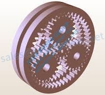 housing with integral band gear provides better concentricity and get rid of speed fluctuations. The casing can be installed with a ventilation module to increase insight speeds and lower operational temperatures.
Output: Available in a solid shaft with optional keyway or an ISO 9409-1 flanged interface. We offer a wide variety of standard Planetary Gear Reduction pinions to install directly to the output style of your choice.
Unit Selection
These reducers are typically selected predicated on the peak cycle forces, which often happen during accelerations and decelerations. These cycle forces depend on the powered load, the speed vs. time profile for the cycle, and any other external forces functioning on the axis.
For application & selection assistance, please call, fax or email us. The application details will be examined by our engineers, who will recommend the very best solution for the application.
Ever-Power Automation’s Gearbox products offer high precision at affordable prices! The Planetary Gearbox item offering contains both In-Line and Right-Position configurations, built with the look goal of offering a cost-effective gearbox, without sacrificing quality. These Planetary Gearboxes can be found in sizes from 40mm to 180mm, ideal for motors which range from NEMA 17 to NEMA 42 and larger. The Spur Gearbox line provides an efficient, cost-effective choice compatible with Ever-Power Automation’s AC Induction Gear Motors. Ever-Power Automation’s Gearboxes can be found in up to 30 different equipment ratios, with torque ratings up to 10,488 in-lbs (167,808 oz-in), and so are compatible with most Servo,
SureGear Planetary Gearboxes for Little Ever-Power Motors
The SureGear PGCN series is a good gearbox value for servo, stepper, and other motion control applications requiring a NEMA size input/output interface. It includes the best quality available for the price point.
Features
Wide variety of ratios (5, 10, 25, 50, and 100:1)
Low backlash of 30 arc-min or less
20,000 hour service life
Free of maintenance; requires no additional lubrication
NEMA sizes 17, 23, and 34
Includes hardware for installation to SureStep stepper motors
Optional shaft bushings designed for mounting to other motors
1-year warranty
Applications
Material handling
Pick and place
Automation
Packaging
Various other motion control applications requiring a Ever-Power input/output
Spur gears are a type of cylindrical equipment, with shafts that are parallel and coplanar, and the teeth that are directly and oriented parallel to the shafts. They’re arguably the simplest and most common type of gear – simple to manufacture and suitable for a range of applications.
One’s tooth of a spur gear have got an involute profile and mesh 1 tooth simultaneously. The involute type implies that spur gears simply generate radial forces (no axial forces), however the approach to tooth meshing causes ruthless on the gear one’s teeth and high noise creation. For this reason, spur gears are usually used for lower swiftness applications, although they could be utilized at almost every speed.
An involute products tooth includes a profile this is the involute of a circle, which implies that since two gears mesh, they get in touch with at an individual point where the involutes satisfy. This aspect movements along the tooth areas as the gears rotate, and the kind of force ( known as the line of activities ) is tangent to both base circles. Hence, the gears stick to the essential regulation of gearing, which promises that the ratio of the gears’ angular velocities must stay continuous through the entire mesh.
Spur gears could be produced from metals such as for example metal or brass, or from plastics such as nylon or polycarbonate. Gears manufactured from plastic produce less sound, but at the trouble of power and loading capacity. Unlike other products types, spur gears don’t encounter high losses due to slippage, therefore they often have high transmission efficiency. Multiple spur gears can be employed in series ( known as a equipment teach ) to attain large reduction ratios.
There are two primary types of spur gears: external and internal. Exterior gears have got the teeth that are cut externally surface of the cylinder. Two external gears mesh with each other and rotate in opposite directions. Internal gears, on the other hand, have teeth that are cut inside surface of the cylinder. An exterior gear sits within the internal equipment, and the gears rotate in the same path. Because the shafts are positioned closer together, internal gear assemblies are smaller sized than external equipment assemblies. Internal gears are mainly used for planetary gear drives.
Spur gears are generally viewed as best for applications that want speed reduction and torque multiplication, such as ball mills and crushing equipment. Examples of high- velocity applications that make use of spur gears – despite their high noise levels – include consumer appliances such as washing machines and blenders. And while noise limits the utilization of spur gears in passenger automobiles, they are often used in aircraft engines, trains, and even bicycles.
In-Line Gearboxes | Inline Planetary Gearbox
Ever-Power offers standard and customized in-collection gearboxes to meet up the needs of nearly any motion or power transfer software. Our inline gearboxes are manufactured for low backlash efficiency. They are precision built to provide reliable assistance in even the many demanding operations.
Read “10 Facts to consider to have the Gearbox YOU WILL NEED” for assistance in finding the best & most effective gear reducer option for the application. “Inertia and the usage of Inertia Figures” provides an example and a formula for coping with inertia in gearbox selection.
Custom Inline Gearbox Solutions
All the inline equipment drive models below could be customized to match your performance and application requirements. Demand a quote on a customized gearbox or get in touch with Ever-Power to go over your unique needs.
High Speed In-Range Spur Gear Box
In-Line Spur
POWERFUL, Low Backlash Velocity Reducer Gearbox
Encoder, Low Backlash
In-Line Low Backlash Taper
In-Line Low Backlash Taper
Servo Gearbox | Planetary Gearbox | Servo Gear Reducer
Epicyclic Servo / Planetary
Inline Planetary Gear Reducer Options
Gearboxes are known by many different titles, including gear drives, reducers, gear reducers, rate reducers, and gearmotors. All conditions can be used pretty much interchangeably when refering to inline planetary equipment reducers.
Spur In-Line Gearboxes
Ever-Power offers a complete line of compact, lightweight spur gear inline planetary gear reducers. These inline gearboxes could be immediate installed to motors or used with shaft coupling. Ratios from 2:1 to 625:1 can be found, with torque values which range from 0.13Nm to 90Nm.
Input quickness: up to 4,000 RPM
Precision machined aluminum housing
Dual ball bearings upon all shafts
Encoder Low Backlash In-Line Gearboxes
These compact, light-weight, low backlash gear drives were created specifically for encoder applications. They have a very low minute of inertia at the shaft input, and are rated for insight speeds up to 3,000 RPM. Gear ratios from 4.96:1 to 3600:1 can be found, in two frame sizes. Synchro cleats for our encoder gearboxes are available from stock.
Result torque: 1 oz.-inch
Backlash: 15 arc-minutes (at any ratio)
Ratios from 4.96:1 to 3600:1
Input boosts to 3,000 RPM
Diameter: 1-1/16” or 1-3/4”
Black anodized aluminum housing
303 stainless gears and shafts
Ball bearings
Low Backlash Inline Taper Gearboxes
Our taper gearmotors are inline planetary equipment reducer boxes with backlash equal to or much better than 8 arc/minute. These inline gearboxes are  designed for applications where space is bound, and are available either as a shaft input or mounted to a 24V DC motor.
Low backlash: ≤8 arc/min. at input
Compact design
Shaft input or with mounted motor
Ratios from 2:1 to 16:1
Output torque ideals from 1.14Nm to 12.7Nm
Epicyclic (Planetary) Servo Gearboxes
The Ever-Power type of internal epicyclic servo reducers are extremely rugged and compact. These planetary gearboxes have fully-machined housings (aluminum or steel), and so are outfitted with ball bearings throughout. Our inline planetary equipment reducers offer flexible motor mounting options and can deliver result torques up to 380 Nm. Ratios from 3:1 to 36:1 can be found.
Low backlash: ≤30 arc/min. at input
Input speeds because high as 3,000 RPM
Precision machined aluminum housings
Dual ball bearings upon all shafts
Available in ratios from 3:1 to 36:1
Output torques since high as 380Nm
Speed Increaser Gearboxes
Our low ratio Encoder gearboxes and inline taper gearboxes may also be utilized as gear swiftness increasers, if needed.
The Ever-Power Advantage: 19 years of Unparalleled Quality
Greased for life
Input speeds since high as 4,000 RPM
Available with equipment ratios up to 3600:1
Customized gearboxes available
Completely machined from block housings
Ball bearings upon all shafts
Ever-Power offers a broad collection of misalignment shaft couplings in ” and metric bore sizes. Inch and metric Precision Surface Shafts can be found from stock.
Contact Us for POWERFUL Inline Gear Drives
Request a quote on a custom made inline gearbox for your application. Contact Ever-Power to discuss your custom requirements.
Correct angle gearboxes (worm and planetary) are tough and built for 90° turns. Inline reducers (parallel shaft and planetary) are an ideal match for motors with high insight speeds, or when gearmotor performance is important. Contact our technical sales staff for help identifying which gearbox alternative is most beneficial for you.
RIGHT ANGLE REDUCERS
WORM GEAR REDUCER
Groschopp’s worm equipment reducers are designed with a hollow bore and allow for a corner switch with optional dual output. The reducers come in 12 ratios ranging from 5:1 to 100:1, with inline planetary gear reducer non-back-drivable ratios 30:1 and higher. Our correct angle gearboxes were created with five mounting options providing versatility when incorporating the reducer into item.
RIGHT ANGLE BEVEL GEARBOX
bevel-right-angle-gearbox
The proper angle bevel gearbox combines the features of our right angle worm and planetary inline reducers. With a solid and efficient right angle configuration, our right angle planetary gearboxes offer a robust solution. The right angle bevel gearbox will come in 18 ratios which range from 5:1 to 1000:1, in fact it is back-drivable at all ratios.
INLINE REDUCERS
I-SERIES PLANETARY GEARBOX
i-series-planetary-gearbox
Our I-Series small planetary gearbox configurations provide the smallest footprint and quietest procedure of our speed reducers. These gearboxes are created to handle varying loads with small backlash. With frame sizes 52cm, 62cm, and 81cm, 12 ratios ranging from 5:1 to 308:1, we’ve a solution to suit your needs. Our 52 frame size can be available with plastic gears for noise-sensitive applications.
INLINE PLANETARY GEARBOX
inline-planetary-gearbox
Our inline planetary gearbox configurations provide the highest efficiency and best output torque of most our swiftness reducers. These gearboxes are created to manage varying loads with little backlash. Planetary equipment reducers operate more quietly than parallel shaft reducers. With 18 ratio options ranging from 5:1 to 1000:1, we have a solution to fit your needs.
PARALLEL SHAFT GEARBOX
parallel-shaft-gearbox
Parallel shaft gearboxes will be the top choice for constant duty applications. Their gear cluster design provides an effective method for dissipating heat. Parallel shaft gearboxes have the shortest length of our inline gear reducer options so they work very well in environments with limited space. Our parallel shaft gear reducers offer an affordable drop-in substitute solution for most small parallel shaft gearmotors.
The typical precision PE-series inline planetary gearheads can be found in 40-155mm frame sizes and offer high torque, low backlash, high input speeds and a little package size with an excellent price/performance ratio.
The PE-series planetary gearbox may be the perfect economy gearbox for all applications where significantly low backlash is not of vital importance.
Markets:
Factory Automation
Packaging Machinery
Food & Beverage
Miscellaneous Industrial
Miscellaneous Manufacturing
Lab/Diagnostic
Life Sciences
Pharma
Features/Benefits:
Frame Sizes: 40 – 155mm
Ratio Options: 3:1 – 64:1
Backlash: to < 7 arc-minutes
Efficiency: up to 97%
Quiet Operation: less than 70db
High Input Speeds: up to 18 000 RPM
Excellent price/performance ratio
High output torques
High quality (ISO 9001)
Any fitting position possible
Simple motor fitting
Life time lubrication
Direction of rotation equidirectional
Balanced motor pinion
Applications:
Industrial Equipments
In-Plant / Automotive Industry Equipments
Robotics
Special Machines
There are three main parts in a planetary gearbox: the sun gear, the earth gears and the ring gear. The gears are attached to the planet carrier which has teeth inside, which may be the ring gear.
Planetary Reducer & Gearmotor
Planetary Gearbox – DieQua Corporation
Planetary gearboxes can easily produce many different reduction ratios because of the different planet gears that revolve around sunlight gear. Planetary gearboxes are made of heavy duty steel such as steel and are in a position to handle huge shock loads well. Nevertheless, different planetary gearboxes are designed for specific acceleration, load and torque capacities. The predominant make use of for planetary gearboxes is certainly in automobiles with automatic transmissions. Unlike manual tranny, in which the operator is responsible for switching gears, automobiles which have automatic transmissions use clutches, brake bands and planetary gearboxes to change the inputs and outputs, thereby adjusting the speeds appropriately.
An automatic transmission contains two complete planetary gearsets placed together into one component. Planetary gearboxes are also used in electric screwdrivers, sprinklers and applications that require huge or multiple reductions from a compact system. Planetary gearboxes are among the many variations of velocity reducers and it is essential that the right mechanism is used. Gearboxes could even be combined to create the desired results and the most typical kinds are helical gear reducers, worm gear reducers and inline equipment reducers.
Planetary gearboxes gain their advantages through their design. Sunlight gear’s central placement allows the planet gears to rotate in the same direction and for the ring gear (the edge of the planet carrier) to carefully turn the same way as the sun gear. In some arrangements sunlight gear can simultaneously switch all the planets as they also engage the band gear. The three components could be the insight, the output or kept stationary, which results in many different reduction ratio options.
In many planetary gearboxes one element is held stationary with another element serving as the input and the other as output. The reduction ratios for planetary gearboxes are dependent upon the number of the teeth in the gears and what elements are involved. Generally, the strain ability and torque increases with the number of planets in the machine because the load is definitely distributed among the gears and there can be low energy waste materials; planetary gearboxes are extremely efficient, averaging between 96 and 98%. The look is complex, however, and difficult to access for repairs or maintenance.
Axial or Inline gearboxes make reference to such types as Helical, Shaft mounted, or planetary designs.
These gearboxes are very common selections for most commercial applications because of their robust nature, high permissible radial forces, closely stepped ratios and low backlash.
Helical gearboxes can typically be within applications requiring high permissible radial force, stepped ratios and low backlash.
Shaft-mounted or otherwise known as Parallel shaft gearboxes provide an inline option with a versatile and space saving foot print. This is actually the only inline gearbox edition with the choice of a hollow output shaft.
Planetary gearboxes are often chosen for hi-tech, high torque, high speed applications requiring severe accuracy.
Helical-worm gearmotors
Due to their style and from being coupled with a helical equipment stage, the helical-worm gearmotors S..DR.. have particularly high efficiency. They are also extremely low-noise and thus avoid high sound emission levels.
Low-noise continuous operation: equipment unit combination optimized regarding efficiency
Do you expect a drive remedy to impress you with its high level of overall performance and efficiency? If so, we’d recommend our high-quality helical-worm gearmotors EP to you. These can be implemented separately in the modular program. In this manner, they offer you an enormous range of sizes, equipment ratios and engine sizes.
However, their greatest strength is certainly their running smoothness and their incredibly low noise development. One thing is for certain – With the helical-worm gearmotors EP you opting for a powerful drive solution that you will hardly also hear.
The overall concept offers you a lot more practical product characteristics and benefits. These include the significantly higher effectiveness of the helical-worm combinations instead of single helical-worm gear units. This is how you save extra energy in the operation of your systems and so are able to noticeably reduce ongoing working costs.
You will have the low-noise helical-worm gearmotors EP. – to fit your person requirements – with an array of AC motors. Furthermore, you can freely configure all the relevant properties. In this way, you can effectively utilize all the benefits offered by this combination of low-noise helical-worm gear unit and performance-optimized motor. Even greater variance may be accomplished because of the optional flange or foot-mounted design and by choosing between solid and hollow shaft.
Save time and money
By opting for among our gearmotors, you are already saving money and time with this selection and project planning. The reason being our modular system allows a multitude of combination options for gear devices and motors. You can consequently reduce operating costs, depend on an extended service life and reap the benefits of simplified maintenance that’s feature of our brand.
Helical-worm gear units
Helical-worm combinations with considerably better efficiency than solitary helical-worm gear units
Very low-noise operation
Available variants:
Foot- or flange-mounted
B5 or B14 flange-mounted
Solid or hollow shaft
Hollow shaft with keyed connection, shrink disk, splined hollow shaft, or Ever-Power
More on helical-worm equipment units of series EP
AC motors
Combine the helical-worm gear unit with this AC motors:
Characteristics
Quiet and reliable transmission of torque
High overload capacity
Hardened steel worm equipment and bronze alloy worm steering wheel provide exceptional strength and lengthy service life.
Optional heavy duty bearings deliver high radial and axial load capacity
High strength cast iron casing (SK02050 – SK43125)
Lightweight, corrosion-resistant aluminium alloy housing (SK02040.1)
Application Specific Solutions
Fields of use
Intralogistics
Material handling
Presses
Version
Solid and Hollow shaft (keyed, shrink disc ) Designs
Available in footed, shaft install or flange mounted configurations
Right Angled gear units
Your advantages
Economical operation
Low noise
High permitted overhung loads
Helical-worm Gearmotor S Series
S series
Ever-Power helical-worm gear products are helical/helical-worm combinations, so they are more efficient than normal helical-worm equipment units. Because of their outstanding efficiency, these drives can be used in every commercial sector and customized to person torque and rate requirements. The decrease ratios afforded by the helical-worm gear stage and the reduced noise levels during procedure make these gearmotors ideal low-cost solutions for basic applications.
Available versions:
Foot-mounted or flange-mounted
B5 or B14 Flange-mounted
Solid or hollow shaft
Hollow shaft with keyed connection, shrink disc, splined hollow shaft
Helical worm geared motors
Tough, compact, eye-catching!
Because of the unique mixture of optimized worm wheel materials with special lubricants, optimized form, this powerful electric motor achieves high degrees of efficiency and torque. The housing machined on all sides enables diverse mounting options. Dual chamber shaft seals are used as standard.
The low contour design makes it ideal for implementing applications e.g. in the meals industry. The housing does not have any recesses, which simplifies cleaning – a particularly essential feature for areas with stringent hygiene requirements.
Technical Data
Number of sizes:6
Power Range:0.12 – 7.5kW
Output torque range:50 – 1,300Nm
Ratio:3 – 3,400
Output option:result shaft, result shaft on both sides, hollow shaft, hollow shaft with shrink disc
Assembly/installation:uniblock, flange, torque arm, foot
Class 12 Helical and hardened and floor worm gears: Provides higher efficiencies and better torque capacity in smaller sizes.
Multiple Input Options: Essential gear motors, in . or metric shafts, NEMA, IEC, and servo adapters provide unmatched drive versatility.
Multiple Output Options: Hollow bores and shrink disks for shaft installation, inch and metric output shafts, mounting pilots and flanges offer a wide range of design solutions.
UNIBLOCK Housing: For optimum helical worm gear motor rigidity universal installation on five sides or with a torque arm.
Sealed for Washdown: Will keep contaminants and water away.
Worldwide Electric motor: Multiple leads and windings for worldwide multi volt/Hz requirements plus modular design to accept brakes, encoders or forced cooling.
EP equipment motors are economical, right-angle, worm-geared motors that install easily in the tightest applications. Economical correct position worm geared motors arranged new standards for reliability, efficiency and economy with unparalleled features which includes hollow shafts in the smallest sizes. An inverter friendly design offers easy integration at this point and a truly future proof alternative. The EP gear electric motor offers total flexibility in mounting choices includes shaft, base, encounter, and flange solutions. The motor terminal box could be mounted in alternative positions rotated in 90º steps around the electric motor frame offering for unparalleled integration options.
EP gear motors adhere to North American and International standards, including NEMA, IEC, CSA, and CE, the EP series allows for worldwide acceptance, a true total option for our global customers.
Excellent protection of IP65 acc. to IEC 529 assures you that the EP series is definitely dust tight and hose evidence,and can be used outdoors or in wet and dusty conditions without the utilization of additional enclosures. Complete rated output is available at the output shaft of the machine.
Product Features
Power ranking up to 5,5 kW.
Torque 25 … 1.000 Nm
Output Speeds 0,2 … 300 min-1
versatile installation possibilities
Completely enclosed, sealed against dust and water spray
Lubrication change 1st after 15000 hrs
Low noise gearing
Mains connection 110 … 690V, 50/60Hz
Enclosure IP65 (Regular), IP66 (Optional)
Connection Regular with CAGE CLAMP®
Additional features:
Connecting with Connect connectors.
With integrated inverter up to 7,5kW.
EP-Mark
CSA, UL, ATEX, GOST, CCC, ISO9001, ISO14001, OHSAS18001
Motors according to EN 60034
Corrosion category based on DIN ISO 12944-5
C1, C2, C3, C4, C5-I, C5-M
Because of the unique mixture of optimized worm wheel material with special lubricants and optimized form, this powerful geared motor achieves high levels of effectiveness and torque. The low contour design helps it be suitable for implementing applications electronic.g. in the food industry. The housing does not have any recesses, which simplifies cleaning – an especially essential feature for areas with stringent hygiene requirements.
Nominal torque: 50 – 1300 Nm
Rated power: 0.12 – 7.5 kW
Ratio: 3 – 3400
The 800BR contains a broad selection of compact, durable helical gear drives with long life performance features and simplified maintenance. The utilization of condition of the artwork helical and worm gear combinations affords optimum efficiency fulfilling a wide variety of ratio requirements. The 800 BR is functionally interchangeable with the majority of major manufacturer’s drives.
SPECIFICATIONS
Dual and triple reduction ratios from 8:1 to 900:1,
4 case sizes – 830, 840, 850, 860
All systems shipped pre-lubed for your particular installation position with KluberSYNTH UH1 6-460
Available in NEMA C-face flanged and immediate input
Projecting and hollow output shafts
Available accessories
Output flange kits
Torque arm kits
Base kits
Output shaft kits
Product Features
Available in nontoxic white-colored (BK) and stainless epoxy finish (SBK)
Available in hollow or projecting output shafts
Double and triple reduction ratios
Flanged or foot mounted
All products adaptable to ground, sidewall or ceiling mounting
Helical worm geared motor
0,12 – 5,5 kW
4 – 996 Nm / 6 – 316 rpm
Stober MGS S helical worm geared motor
Efficient small right-angle geared engine. A favorably priced substitute for the standard duties anticipated of a right-angle drive.
5 gear sizes (S0 to S4).
Motor power 0.12 to 5.5 kW.
Rated torque of 23 to 800 Nm.
Gear ratios from we = 6 to 680.
Backlash smaller than 20 arcmin.
Modular, torsionally stiff , leak-proof design.
Helical worm geared motors offered with:
Solid shaft with keyway.
Hollow shaft with keyway, optional with cover.
Hollow shaft with shrink disk, optional with cover.
Gear device and AC electric motor are directly flange mounted, the pinion is on the motor shaft. This integrated small design can be an essential element for the high precision and the extraordinary stiffness of EP geared motors.
For vector-controlled inverter operation use of an incremental encoder is provided for as regular.
Worm gearboxes and helical worm gearboxes / geared motors (S and SS)
The amount of efficiency in Ever-Power powerful worm gearboxes and helical worm gearboxes is more than 90%. All worm shafts are manufactured from case hardened alloy steel and the flanks are precision floor. The worm tires are made from particular wear-resistant bronze. Helical worm gears are equipped with a helical gear. Worm gears with shrink disc, torque limiter, along with adjustable backlash styles are also component of our standard product range.
Worm gearboxes and helical worm gearboxes type S and SS are high-Functionality gearboxes in universal design. The housings are made from top quality cast iron. The rugget wall space and inner ribbing ensure incredibly torsional stiff and sound dampening housings. The external ripping offers a rapid heat conducting.
Type S und SS
Technical characteristics:
Optimised size/performance ratio
Designed for permanent procedure under rough circumstances
Above average lifespan
Housing produced from top quality grey cast iron with durable walls and internal ribbing
Intense torsional resistance and low noise
Case hardened worm shafts and worms with precision floor flanks
Worm wheels created from unique bronze
Superior smooth operation
Space saving angular drive
Helical worm gearboxes equipped with helical gear wheel Low engine speeds
Options:
Basic mounting, flange mounting or universal design
Output shaft available since solid shaft or hollow shaft
Shrink disc, torque limiter,as well as adjustable backlash
Second shaft end for fitting encoders or brakes
Torque arm
IEC-adaptor
NEMA version
Free input shaft
ATEX specification according to directive 94/9/EG
Cycloidal gearboxes
Cycloidal gearboxes or reducers consist of four fundamental components: a high-speed input shaft, a single or substance cycloidal cam, cam followers or rollers, and a slow-speed output shaft. The input shaft attaches to an eccentric drive member that induces eccentric rotation of the cycloidal cam. In compound reducers, the first an eye on the cycloidal cam lobes engages cam fans in the housing. Cylindrical cam followers become teeth on the internal gear, and the number of cam supporters exceeds the amount of cam lobes. The second track of substance cam lobes engages with cam followers on the output shaft and transforms the cam’s eccentric rotation into concentric rotation of the result shaft, thus raising torque and reducing quickness.
Compound cycloidal gearboxes provide ratios ranging from only 10:1 to 300:1 without stacking phases, as in regular planetary gearboxes. The gearbox’s compound reduction and will be calculated using:
where nhsg = the number of followers or rollers in the fixed housing and nops = the quantity for followers or rollers in the sluggish swiftness output shaft (flange).
There are several commercial variations of cycloidal reducers. And unlike planetary gearboxes where variations derive from gear geometry, heat therapy, and finishing procedures, cycloidal variations share simple design concepts but generate cycloidal motion in different ways.
Planetary gearboxes
Planetary gearboxes are made up of three fundamental force-transmitting elements: a sun gear, three or even more satellite or world gears, and an internal ring gear. In a typical gearbox, the sun gear attaches to the insight shaft, which is linked to the servomotor. Sunlight gear transmits electric motor rotation to the satellites which, in turn, rotate inside the stationary ring gear. The ring equipment is area of the gearbox casing. Satellite gears rotate on rigid shafts linked to the earth carrier and cause the planet carrier to rotate and, thus, turn the result shaft. The gearbox provides output shaft higher torque and lower rpm.
Planetary gearboxes generally have solitary or two-equipment stages for reduction ratios which range from 3:1 to 100:1. A third stage could be added for actually higher ratios, nonetheless it is not common.
The ratio of a planetary gearbox is calculated using the following formula:where nring = the number of teeth in the internal ring gear and nsun = the amount of teeth in the pinion (input) gear.
Comparing the two
When deciding between cycloidal and planetary gearboxes, engineers should initial consider the precision needed in the application form. If backlash and positioning accuracy are necessary, then cycloidal gearboxes provide most suitable choice. Removing backlash may also help the servomotor manage high-cycle, high-frequency moves.
Next, consider the ratio. Engineers can do that by optimizing the reflected load/gearbox inertia and speed for the servomotor. In ratios from 3:1 to 100:1, planetary gearboxes offer the greatest torque density, weight, and precision. In fact, few cycloidal reducers provide ratios below 30:1. In ratios from 11:1 to 100:1, planetary or cycloidal reducers may be used. Nevertheless, if the mandatory ratio goes beyond 100:1, cycloidal gearboxes keep advantages because stacking phases is unnecessary, therefore the gearbox could be shorter and less expensive.
Finally, consider size. Many manufacturers offer square-framed planetary gearboxes that mate precisely with servomotors. But planetary gearboxes grow in length from solitary to two and three-stage styles as needed equipment ratios go from less than 10:1 to between 11:1 and 100:1, and then to greater than 100:1, respectively.
Conversely, cycloidal reducers are bigger in diameter for the same torque but are not for as long. The compound reduction cycloidal gear teach handles all ratios within the same package size, so higher-ratio cycloidal equipment boxes become actually shorter than planetary variations with the same ratios.
Backlash, ratio, and size provide engineers with an initial gearbox selection. But selecting the most appropriate gearbox also consists of bearing capability, torsional stiffness, shock loads, environmental conditions, duty routine, and life.
From a mechanical perspective, gearboxes have grown to be somewhat of accessories to servomotors. For gearboxes to execute properly and provide engineers with a stability of performance, existence, and worth, sizing and selection ought to be determined from the strain side back again to the motor as opposed to the motor out.
Both cycloidal and planetary reducers work in any industry that uses servos or stepper motors. And although both are epicyclical reducers, the distinctions between many planetary gearboxes stem more from gear geometry and manufacturing procedures instead of principles of operation. But cycloidal reducers are more diverse and share small in common with one another. There are advantages in each and engineers should think about the strengths and weaknesses when selecting one over the various other.
Benefits of planetary gearboxes
• High torque density
• Load distribution and posting between planet gears
• Smooth operation
• High efficiency
• Low input inertia
• Low backlash
• Low cost
Great things about cycloidal gearboxes
• Zero or very-low backlash remains relatively constant during lifestyle of the application
• Rolling rather than sliding contact
• Low wear
• Shock-load capacity
• Torsional stiffness
• Flat, pancake design
• Ratios exceeding 200:1 in a concise size
• Quiet operation
The need for gearboxes
There are three basic reasons to employ a gearbox:
Inertia matching. The most typical reason for choosing the gearbox is to control inertia in highly dynamic circumstances. Servomotors can only just control up to 10 times their personal inertia. But if response period is critical, the  engine should control significantly less than four moments its own inertia.
Speed reduction, Servomotors run more efficiently at higher speeds. Gearboxes help keep motors working at their optimum speeds.
Torque magnification. Gearboxes offer mechanical advantage by not only decreasing acceleration but also increasing result torque.
The EP 3000 and our related products that use cycloidal gearing technology deliver the most robust solution in the most compact footprint. The primary power train is made up of an eccentric roller bearing that drives a wheel around a set of internal pins, keeping the reduction high and the rotational inertia low. The wheel incorporates a curved tooth profile instead of the more traditional involute tooth profile, which removes shear Cycloidal gearbox forces at any stage of contact. This style introduces compression forces, rather than those shear forces that could can be found with an involute equipment mesh. That provides a number of performance benefits such as high shock load capacity (>500% of ranking), minimal friction and use, lower mechanical service elements, among many others. The cycloidal design also has a large output shaft bearing span, which provides exceptional overhung load capabilities without requiring any additional expensive components.
Cycloidal advantages over additional styles of gearing;
Able to handle larger “shock” loads (>500%) of rating compared to worm, helical, etc.
High reduction ratios and torque density in a concise dimensional footprint
Exceptional “built-in” overhung load carrying capability
High efficiency (>95%) per reduction stage
Minimal reflected inertia to electric motor for longer service life
Just ridiculously rugged as all get-out
The entire EP design proves to be extremely durable, and it needs minimal maintenance following installation. The EP is the most reliable reducer in the industrial marketplace, in fact it is a perfect suit for applications in weighty industry such as for example oil & gas, primary and secondary steel processing, industrial food production, metal trimming and forming machinery, wastewater treatment, extrusion devices, among others.
Ever-Electric power is engaged in neuro-scientific manufacturing Bevel Planetary Equipment Box with optimum style feature and latest technology of enhancing the geometrical precision of the apparatus teeth account with the team of experienced experts. We are a leading manufacturer of planetary gearbox in China….
Ever-Electricity is engaged in neuro-scientific manufacturing Bevel Planetary Equipment Box with optimum design feature and latest technology of improving  the geometrical accuracy of the gear teeth account with the crew of experienced pros. We are a leading supplier of planetary gearbox in China.
• Reduction Ratios : 3: 1 to 50000 : 1
• Ranked Torque : 0.5 Kg-m to 100000 Kg-m
• Input Vitality : 0.25 HP to 100 HP
• Input Speed : 1440 RPM, 960 RPM, 720 RPM
• Prime Mover : Electric Motor / Hydraulic Motor
• nput Type : Hollow Source/ Free
Ever-Power Bevel Planetary Gear Boxes consist of an interior toothed Ring Equipment to which are set 3 Planet mounted on earth carrier engaging also with the Sun Gear (Pinion) and reduced Productivity velocity is taken through Planet Carrier and Ring Gear is remain stationary. Output shaft retaining the same way of rotation as Input.
Ever-Power Bevel Planetary Equipment Boxes trusted in Material Handling Equipments, Mechanical Industry, Sugar Bevel Planetary Gearbox Sector, Cement Industry, Chemical Industry, Food Industry, Construction Sector, Agricultural Industry, Power Sector, Mobile Cranes and Over head Cranes etc
Ever-Power Gear Transmissions offers Foot Mounted Planetary Gearboxes, Flange Mounted Planetary Gearboxes, Shaft Mounted Planetary Gearboxes, Agitator Mounted Planetary Gearboxes, Planetary Geared Electric motor, Planetary Winch Drive, Planetary Creep Drive, Planetary Sugar Crystallizer Get, Bevel – Planetary Drive, Heavy duty Planetary Drive ,BESPOKE BUILD Planetary Gearboxes, Comparative Planetary Gearboxes to Imported Gearboxes
Ever-Power Planetary Equipment Boxes are Solid Source, Solid Output, Hollow Source, Hollow Output, Solid Output Splined Shaft, Solid Suggestions Splined Shaft, Hollow Outcome Splined Shaft, Hollow Type Splined Shaft. (IS:3665-1966 and DIN 5480)
Ever-Power Bevel Planetary Equipment Boxes are created from superior quality raw material such as for example Alloy Steel EN8/EN9, EN19, EN24/42,EN36c,, 16 MnCr5, CrMo4, SAE8620, MnCr/20, MnCr5/EN353, Cast Steel IS:1030, Gr2, IS :2707 Gr2, Cast Iron CIGR 25/30, GGG40/50 OR SGI Case Carburised Metal and Hardened Steel.
Ever-Power Bevel Planetary Equipment Boxes will be highly efficient, Compact in Size, having large Shock Load Capacity, ideal for Continuous Cyclic Loads, Reversible Drive, Installation in any Position, Torque Multiplication, Input and Output Rotation found in same direction
Hot Tags: bevel planetary gearbox, China, suppliers, manufacturers, factory, wholesale, buy, manufactured in China
Size above PL120(including) high torque goods adopt integral double wall structure planet pinion carrier, precision and improve the output strength.
Hoop clamp coupling possess five connection ways suited to different application environments:
Size above PL120(including) precision and high strength integral inner gear housing, processed in a single station, which eliminate the cumulative error and assembling mistake of split type. Remove casting process; adopt hot forging process, that may reduce the blank material defects.
The meshing equipment adopt shaving procedure after carburizing and quenching, which better to make gear area smooth and high precision, reduce the temperature rising caused by gear surface gluing and friction.
Features
1.High Precision
Standard backlash is 3 arc-min,ideal for precision control
2.High rigidity&torque
High rigidity&torque were attained by uncaged needle roller bearings.
3.High load capacity
Adopting taper roller bearing for the primary output shaft to increase radial and axial load
4.Adapter-bushing connection
Can be mounted on any motor across the world.
5.No grease leakage
Perfect solution using huge viscosity anti-separation grease.
6.Maintenance-free
No need to replace the grease for the life span of the unit.Could be attached in virtually any position.
Application
Trusted in printer,conveyer-belt,gantry robot,auto packing sealing machine,packing machine,dispenser robot,loader robot,turret head,etc.
High-Quality Right Angle Gear Drives are created for efficiency, quiet operation, and long service life. SDP/SI offers a broad collection of Right Angle Equipment Drives in various configurations, materials, working speeds, and multiple ratios. Standard catalog products include precision and commercial quality gear drives provided in both inch and metric sizes. For adjustments or custom designs call and talk with a SDP/SI applications engineer.
Our offering includes, but is not limited to the following:
Miniature sized Right Position Gear Drives, 1 inch square, are ideal for compact designs that require low backlash and insight boosts to 2000 rpm.
When weight can be an issue, get Correct Angle Bevel Gear Drives that feature a lightweight casing of PTMT Polyester 30% glass filled, precision floor right angle worm gearbox STAINLESS shafts, sintered bronze bearings and molded nylon gears.
Right Angle Worm Gear Drives accommodate input speeds up to 2000 rpm and so are obtainable in gear ratios: 5:1, 10:1 and 20:1.
Right Angle and Dual Helical Equipment Drives can be found in two models, light-duty, rated boosts to 600 rpm and heavy duty, rated speeds up to 1725 rpm.
An economy series of Right Angle Bevel Gear Drives is offered in 1:1 and 2:1 ratios and rated speeds up to 500 rpm.
E Series Right Angle
The Ever-Power E Series is a high efficiency, right angle gear reducer made for increased torque density, reduced inventory and improved efficiency. By utilizing modified helical-bevel technology, the E Series can operate at 90% effectiveness and can provide up to 60% higher torque than a typical worm equipment reducer. Through various accessories and modular elements, the Electronic Series recreates the essential dimensions of a standard worm gearbox and the opportunity to reduce inventory.
Right-angle Worm Gearboxes
4 sizes available with ratings to 27 HP.
Available in single, dual & triple reduction.
Ratings from 7.8:1 to 59:1.
EP-worm-gearboxsEP Series variants, worm gear family
Ever-Power has been in the forefront of developing gear technology to fill the requirements of our OEM customers. Our close partnerships with our installed customer bottom provided much insight to their evolving need for more high-precision right-position gearing options. In order to fill that require, Ever-Power expanded upon our right angle item offering to include a variety of high-precision worm gearboxes, known as our EP Series.
These servo grade speed reducers are ideal for the most difficult of movement control applications. Each series incorporates a globoidal worm equipment mesh design to be able to achieve the torque handling capability and the highest levels of precision our SHIMPO customers attended to anticipate from us. The insight design of our EP right-angle gearbox applies the same idea of motor modularity that is common across our High Precision item family, meaning our customers and distribution companions get the same degree of flexibility, product variety, and overall availability that is unparalleled within our industry.
Benefits of the EP Series system design;
Quiet operation, compared to other competitive worm gearing
Compact, with precise reduction ratios
High torsional rigidity and torque carrying capacity
A lower life expectancy backlash feature, unique among right-angle gearheads
Industry standard hollow bore output with other shafted options
Extremely lightweight, optimized construction
Maintenance free, lubrication for lifetime
These right-angle servo grade gearboxes are ideal for applications within custom assembly and test systems, packaging equipment, metallic cutting and metal forming machinery, general purpose auto, among numerous others. If the application requires the small footprint of a right-angle worm gear without sacrificing on the efficiency, contact Ever-Power about the EP Series today.
Standard Right Angle Gearbox Features
All ratios built with right-hand worm gears
Load capacity unaffected simply by direction and rotation
Selection of mounting Options
Upon Request:
Left-Hand Gears
STAINLESS Input/Output Shafts
Solid or Hollow Output Shaft
Decide on a Gearbox or Speed Reducer
Worm Gear Acceleration Reducers
sw-1-parent.jpg
SW-1
SWB-5 & SW-5
Right Angle Miter Equipment Drives
miter-gear-parent.jpg
Miter Gear Drives
Mini Right Angle Helical Gear Drives
miniature-right-angle-parent.jpg
RA-200
RA-300
Custom Speed Reducers
custom-speed-reducer-parent.jpg
Custom Speed Reducers
GEARBOX REDUCERS
Correct angle gearboxes (worm and planetary) are tough and built for 90° turns. Inline reducers (parallel shaft and planetary) are a perfect match for motors with high input speeds, or when gearmotor performance is important. Contact our technical sales staff for help identifying which gearbox answer is most beneficial for you.
RIGHT ANGLE REDUCERS
WORM GEAR REDUCER
EP’s worm gear reducers are designed with a hollow bore and invite for a corner convert with optional dual result. The reducers can be found in 12 ratios which range from 5:1 to 100:1, with non-back-drivable ratios 30:1 and higher. Our correct angle gearboxes are designed with five mounting choices providing flexibility when incorporating the reducer into product.
RIGHT ANGLE BEVEL GEARBOX
bevel-right-angle-gearbox
The right angle bevel gearbox combines the features of our correct angle worm and planetary inline reducers. With a good and efficient right angle configuration, our right angle planetary gearboxes offer a robust solution. The proper angle bevel gearbox will come in 18 ratios ranging from 5:1 to 1000:1, and it is back-drivable at all ratios.
INLINE REDUCERS
I-SERIES PLANETARY GEARBOX
i-series-planetary-gearbox
Our I-Series little planetary gearbox configurations provide the smallest footprint and quietest procedure of our rate reducers. These gearboxes are designed to deal with varying loads with little backlash. With frame sizes 52cm, 62cm, and 81cm, 12 ratios which range from 5:1 to 308:1, we have a solution to suit your needs. Our 52 frame size can be available with plastic-type material gears for noise-sensitive applications.
INLINE PLANETARY GEARBOX
inline-planetary-gearbox
Our inline planetary gearbox configurations supply the highest effectiveness and best result torque of most our speed reducers. These gearboxes are created to manage varying loads with small backlash. Planetary equipment reducers operate more quietly than parallel shaft reducers. With 18 ratio options which range from 5:1 to 1000:1, we’ve a solution to fit your needs.
PARALLEL SHAFT GEARBOX
parallel-shaft-gearbox
Parallel shaft gearboxes will be the best choice for continuous duty applications. Their gear cluster design provides a highly effective method for dissipating heat. Parallel shaft gearboxes possess the shortest amount of our inline gear reducer options therefore they work well in environments with limited space. Our parallel shaft equipment reducers provide an affordable drop-in substitute solution for most little parallel shaft gearmotors.
Wormwheel gearboxes go by several names, including 90-degree gearboxes, right position gearboxes, speed reducers, worm equipment reducers and worm drive gearboxes. Gear reduction boxes feature a gear arrangement when a gear in the type of a screw, also called a worm, meshes with a worm gear. These gears are usually created from bronze and the worms are steel or stainless steel.
While worm gears act like a spur gear, the worm gearboxes are considerably smaller than other equipment reduction boxes. A principal benefit of worm gear reducers is definitely that they produce an output that is 90° from the insight and can be utilized to transmit higher torque or decrease rotational speed. Most often, a worm gearbox has right hand threads; to change the direction of the output, a left-hands thread worm gearbox is necessary.
Worldwide HdRS133-10/1-R Cast Iron Right Angle Worm Gear Reducer 10:1 Ratio
Cast Iron Worm Equipment Reducers can be found in center distances 1.33 – 3.25 inches in ratio’s from 5:1 to 60:1. The systems have a one piece #Fc20 all cast iron housing, NEMA motor quill style input flanges or shaft inputs, come pre-filled with synthetic oil and also have a 12 months warranty.
Features:
Tapered roller bearings upon the input and output shafts
Embedded double-lip oil seals
Anti-rust primer applied outside and inside of the gearbox
Air dry special black paint
Product Specifications
OUTPUT SPEED (RPM) 175
OVERHUNG LOAD LBS. 300
EFFICIENCY 86
BRAND EP
MANUFACTURERS PART NUMBER HdRS133-10/1-R
CROSS REFERENCE Boston 713; Grove B213
DESCRIPTION Cast Iron Correct Ange Worm Gear Reducer
BACKLASH (FT.) (ANGULAR MINUTES) 27
OUTPUT SHAFT THRUST LOAD (Pounds.) 300
MAX INPUT HP 0.77
MAX TORQUE (IN-LBS.) 247
WCD CENTER INCHES 1.33
GEAR RATIO 10:1
Ever-Power EP series triple-reduction worm gear rate reducers are available in ratios from 5000:1 to 175,000:1 and center distances from 7” to 20” (larger sizes on request). Result torque ranges from 33,000 in lbs. for the 7” CD EP-70 to 582,900 in pounds for the EP-200. Mechanical HP insight requirements are from 0.09 HP for the 175,000:1 7 in CD reducer to 6.25 HP for the 5000:1 20” CD unit. These reducers are available in four configurations: horizontal, vertical, shafted, and shaft installed.
 These reducers are ideal for water/waste-water devices drive applications such as thickeners and clarifiers, which need a vertical down shaft. Other obtainable configurations also make Ever-Power triple reduction reducers perfect for make use of on mixers, elevators, solar panels, astronomical telescopes, indexing tables, hoists, conveyors, or various other process or materials handling systems where huge torques/slower speeds are needed.
These reducers are also obtainable with a helical principal reduction stage and are termed the HDVM series
Enclosed Gears / Gearboxes
Enclosed gears, also called gearboxes or acceleration reducers, are open gears within a housing. The casing supports bearings and shafts, holds in lubricants, and protects the elements from surrounding circumstances. Gearboxes are available in an array of load capacities and quickness ratios.
The purpose of a gearbox is to improve or reduce speed. Consequently, torque output will be the inverse of the function. If the enclosed drive is usually a rate reducer, the torque output will increase; if the drive raises speed, the torque output will reduce. Gear drive selection factors include: shaft orientation, velocity ratio, design type, character of load, gear rating, environment, mounting position, operating temperature range, and lubrication.
Basic Types of Gearboxes
Worm Gear Speed Reducers
A single reduction velocity reducer can achieve up to 100:1 reduction ratio in a little package. Referred to as right angle drives, these consist of a cylindrical worm with screw threads and a worm. With an individual start worm, the worm gear advances only 1 tooth for each 360-degree change of the worm. So, regardless of the worm’s size, the gear ratio is the ‘size of the worm equipment to 1′. Higher decrease ratios can be created through the use of double and triple reduction ratios.
Helical Gear Speed Reducers
Provide high-efficiency speed decrease through 1, 2, 3, or 4 sets of gears. Power is definitely transmitted from a high-swiftness pinion to a slower-speed gear. Helical gears usually operate with their shafts parallel to each other. Both most common types will be the concentric (input and result shafts are in series) and parallel shaft (input and result shafts are offset). Single-stage helical gear reducers are usually used for equipment ratios up to about 8:1. Where cheaper speeds and higher ratios are necessary, double, triple, and quadruple equipment reduction stages can be used.
EP 700 Series STAINLESS Worm Gear Rate Reducers | Ever-Power Gear
THE INITIAL Stainless Reducer
The Ever-Power Gear 700 Series Worm Gear Rate Reducer is a foundation in food and beverage applications for decades. As a head in worm gear technology, Ever-Power Gear continues to improve product efficiency by developing innovative designs to meet up more stringent demands and anticipated tightening of federal rules in the meals and beverage industry.
Blending trusted 700 Series worm gearing with a forward thinking new exterior style, the stainless steel 700 series has been optimized to withstand the harshest washdown circumstances. The units feature reliable 700 Series worm gearing, a 316 stainless rounded casing with smooth uninterrupted areas designed to prevent particle accumulation and pooling fluids, dual lipped shaft seals, covers for all hardware and counter bored holes.
NSF Certified Logo
Sure, a stainless gearbox costs greater than a painted 1, but purchasing a more corrosion resistant gearbox saves cash and makes the most sense over time. Unmatched product efficiency in highly caustic washdown applications combined with first class customer service makes Ever-Power Gear your 1st choice for velocity reducers and gearmotors!
Product Features
NSF International Certified
316 stainless steel housing, bearing carriers and flanges
303 stainless output shafts
Rounded housing eliminates practically all smooth surfaces and prevents foreign matter accumulation or standing up fluid
Elimination of all exposed hardware promotes soft surfaces to optimize wash down effectiveness
Lubed forever with H1 rated food quality lubricant Klubersynth UH1 6-460
Flange style incorporates jack bolt holes to facilitate easy motor-reducer separation
5:1 – 100:1 Single Reduction
100:1 – 3600:1 – Double Reduction
Motor flange style incorporates an O-ring to reduce ingress of particles or fluids
Polished matte complete maintains clean appearance throughout operation
Optional high pressure washdown seal available
Obtainable in hollow and solid result shaft
Stainless Steel, Heavy-duty Correct angle (SSHdR) series worm gearboxes are created with 304 stainless steel. All reducer surfaces are polished and curved to avoid organism growth on surfaces. SSHdR series Hollow Result Bore reducers are available in speed ratios which range from 5:1 to 60:1 with imperial center distances ranging from 1.75 to 3.25 inches. Also, our stainless gearboxes come pre-loaded with EP meals grade lubricant.
“EP” series Flange Insight – Hollow Bore Output series stainless steel correct angle worm gear reducers are stocked as completed goods with hollow output bore sizes which range from 1” to 2-3/16” with available center distances ranging from 1.75 to 3.25 inches. All motor input flanges are NEMA C-face quill style designs and each unit comes pre-filled with EP meals grade lubricant. Stainless Steel bushing kits are sold separately to allow for a lot more head shaft size configurations.
Product Features
5:1 – 60:1 ratios
Center distances which range from 1.75 to 3.25 inches
304 stainless steel housing, covers and flanges
Smooth, polished areas and etched nameplate
Internal bladder functions as a breather and effectively dispels heat
Double-lipped VITON oil seals (at output)
15CrMo4 NEMA quill insight with carburizing heat treatment
CuSn12Ni2 bronze alloy worm wheel with high efficiency gear tooth configuration
RoHS plastic material covers supplied to fill up unused mounting slots
0-ring provided upon input flange to avoid moisture intrusion
Pre-stuffed with Mobil CIBUS 460 H1 food grade lubricant
Interchangeability with major brands
1-year warranty
STAINLESS (SS Series)
Grove Gear STAINLESS gear reducers offer superior corrosion safety. They are rust proof and in a position to withstand the harshest conditions. The stainless housing, cover and exterior hardware offer an exceedingly long life.
Center distances from 1.33” through 3.250”.
6 sizes available with ratings to 17 HP.
Obtainable in single and double reduction.
Ratios from 5:1 to 3600:1.
316 stainless steel casing and covers to withstand extreme environments.
Factory-filled with superior Mobil Glygoyle 460 polyalkalene glycol lubricant
Vent-free “sealed-for-life” design with Enviroseal technology.
EP dual lip seals provide extended lifestyle through increased resistance to temperature, abrasion and chemicals.
O-ring on encounter of input flange provides a positive seal against moisture intrusion.
303 stainless output shaft.
Worms are cut, heat-treated, Stainless steel worm reducers surface and polished to supply efficient, quiet operation.
All  units are 100% run and leak tested at the factory to insure you get the highest quality product.
Ultimate application versatility with all-angle installation provisions, the widest selection of item bases and flanges and the biggest collection of stock reducer styles.
Mounting dimensions are interchangeable with many industry standard reducers.
EP Stainless Steel
Right Angle / Large Washdown Duty STAINLESS Speed Reducer
This Stainless Steel reducer is made for Heavy Duty Washdown applications and is resistant to numerous forms of wear. This is what you would like to use for severe environmental conditions.
STAINLESS WORM GEARBOX
Adhere to HACCP and EHEDG regulations
It is becoming more and more difficult to get your machine to meet the HACCP and EHEDG rules, while your visitors vulue this a lot more. The stainless worm gearbox drive program Ever-Power allows you to stay affordable but meet tcustomer demants.
The Ever-Power stainless worm gearbox types are made to meet the guidelines. As a result, they are resistant to an intensive cleaning regime, is made of hygienic components and are also dead spots, and horizontal surfaces as much as possible, avoided. Of training course, the material of the products is stainless.
Output torques of 40Nm up to 160Nm.
Output shaft sizes of 18mm up to 25mm.
Input flanges 63B14a up to 90B5.
Reduction ratios of we=7,5 up to i=100.
Food grade oil, meals grade seals and hygienic design.
Material worm wheel: Cu bronze SN12 Ni2 (UNI7013-10), materials hardened steel worm shaft and ground profile ZI (UNI4760).
Belastingscapacitieiten conformity: ISO.14521, DIN.3996, BS 721, AGMA 6034, ISO 6336, DIN 3990, DIN 743, ISO 281.
STAINLESS STEEL WORM GEAR SPEED REDUCERS
◦ Right angle worm gearbox
◦ Ratio 5:1 to 60:1
◦ Size 206 to 325 (2.06″ to 3.25″ between input and output shaft)
◦ Created for heavy-duty washdown
◦ Rust free casing, flange, and shafts are perfect for food industry
◦ Ideal for tough conditions and corrosive applications
◦ Internal bladder adjusts to heat and pressure – No need for a surface breather
◦ Heat-treated metal worm shaft w/ ground thread
◦ Aluminum bronze (ALBC3) worm wheel
◦ Polished matte finish
◦ Top quality double lip oil seals
◦ Input flange O-band repels external moisture
◦ USDA H1 food grade lubricant : MOBIL SHC CIBUS 460
◦ Appropriate for 56C, 145TC and 182/4TC Engine Inputs
◦ One year limited warranty
Ever-Power STAINLESS S Series right-position worm reducer is perfect for harsh washdown circumstances in food processing or other applications with high temperature/high pressure sprays. The S Series comes regular given synthetic oil for lifetime lubrication and is made up of a stainless steel housing that is designed for safety in washdown applications, also designed for multiple mounting configurations.
Hygienic stainless BJ worm gearboxes
Ever-Power provides a self-produced stainless gearbox range of top quality. The series was developed specifically for the food industry and additional industries where there are consistently stringent requirements for the resistance of the materials and the easy-to-clean design.
The gearboxes are made from a smooth stainless gear housing, they are lifestyle lubricated and may of course be given oil approved for the food industry. Essential oil seals are standard manufactured from nitrile rubber.
To reduce the chance of bacterial development, the design is characterised by smooth machined surfaces without unnecessary flanges, recesses and mounting holes. It is also possible to purchase the gearboxes with torque arm, side flange, free worm and plug-in shaft. Other adjustments are performed on demand including such as stainless spindle gears.
In cases where you want a complete hygienic gear engine, we can provide the EP-gearboxes fitted with stainless AC or servo motor.
Resistant to cleaning with drinking water under pressure
The protection of the gearboxes is IP65, and for stainless motors it is IP66. This means that the products could be cleaned with water under pressure from all directions. To attain an overall protection of IP66 by assembly of gearboxes and engine, you must make use of a gasket of nitrile rubber for the joint. This implies that the gear motors are perfect for free mounting with out a traditional stainless basic safety cover in areas where hygiene requirements are highest. Hidden sources of pollution can therefore be avoided.
The gearboxes are as standard given a center distance of 31, 42, 61 and 99 mm with gear ratios from 5:1 to 100:1 and with an output torque as high as 900 Nm.
Stainless steel worm gearbox
Ratios
Maximum output torque
[Nm]
Housing design
Series 31
5:1 – 75:1
13.2
Stainless steel
Series 42
5.4:1 – 75:1
57
Stainless steel
Series 61
7:1 – 100:1
208
Stainless steel
Series 79
7:1 – 60:1
337
Stainless steel
Series 99
7:1 – 100:1
891
Item selection brochures available below:
Full Integral Horsepower Product Catalog
Worm Product Selection Table
S 45 Series – 0.25 – 1HP, 97 – 450in-lbs, 17.2 – 250RPM
S 50 Series – 0.25 – 2HP, 199 – 567in-lbs, 17.5 – 250 RPM
S 63 Series – 0.25 – 2HP, 209 – 1199in-lbs, 18.6 – 250RPM
S 85 Series – 0.5 – 5HP, 666 – 2353in-lbs, 18.2 – 250RPM
Extra flange and shaft inserts available and may be requested during product selection. To order, please get in touch with Bison at 1.800.ATBISON (282.4766) and ask to talk with an Automation Professional. Online selection and buying coming soon!
Stainless Steel Solutions
Effective, Clean Solutions with a Stainless Reputation.
Ever-Power Drive’s stainless precision movement gearboxes are designed for sterile manufacturing conditions. The product’s smooth surface area and curved contour permits easy cleaning and bacteria-free surfaces, ideal for food processing and pharmaceutical applications. The merchandise is designed and ranked to IP69k offering maximum safety against contaminant ingress in addition to leak free operation.
Catalogued models of Ever-Power Gear’s well-known stainless 700 Series rate reducers are now available with standard 2-day delivery. Process improvements possess yielded the industry’s best standard lead time for stainless steel worm gear reducers.
Ever-Power Gear’s SS700 Series, the initial “domed crown” stainless reducers, are created for maximum corrosion resistance and superior efficiency in high-pressure food processing and packaging washdown applications.
A convenient after hours/holiday hotline can be available for emergency orders. Catalogued SS700 Series versions are stocked at local and regional distribution centers to ensure fast delivery.
All SS700 versions are NSF Authorized and also have many maintenance-friendly features including electropolished exterior finish, sealed electric motor flange, and covered hardware. To avoid miniscule niches that can web host microbial contamination, the nameplate provides been laser marked to supply a smooth uninterrupted surface area. A large internal oil reservoir, filled with H1 food-quality lubricant (Klubersynth UH 1 6-460) and sealed forever, allows for a wide range of operating temperature ranges and extended service life.
A timing belt idler pulley allows the timing belt to be routed as essential  to speak to the timing gears upon the crankshaft and camshafts. The timing belt idler maintains some tension on the belt, but the tension primarily originates from the timing belt tensioner assembly. A timing belt idler is merely a pulley mounted on a Timing Belt Pulley bracket with a bearing between to permit it to spin freely. If the bearing offers worn out or it isn’t properly lubricated, the timing belt idler may fail. Debris inside of the engine or the timing belt itself could also harm the pulley. If you’re replacing your timing belt, consider changing your timing belt idler, pulley, and tensioner simultaneously. Ever-power carries all of the parts you need for your timing belt restoration.
Product Overview
Timing Belt Pulley; Ever-power PowerTiming Parts for those who want to displace individual parts. Components consist of automatic, manual and hydraulic tensioners and idler pulleys. Only OE parts for the most famous and problematic applications.Ever-power – Driven By Probability
For the past century Ever-power has been powering improvement among the worlds leading parts producers in the automotive industry, dealing with virtually every Original Equipment Manufacturer worldwide to design products for new automobiles as they are being developed. These strong relationships as well as Ever-power commitment to continuous innovation allow us to offer a complete type of OE quality items for the Aftermarket. From Timing Belts to Micro-V AT Belts, Tensioners and Hose, for both import and domestic automobiles, install confidently, install Ever-power.
Your Ever-power will be happy to know that the seek out the proper Timing Idler products you’ve been looking for has ended! Advance Auto Parts has 2 different Timing Idler for your vehicle, ready for shipping or in-store pick up. The best component is, our Ever-power Timing Idler items start from as little as $26.81.
When it comes to your Ever-power, you want parts and products from only trusted brands. At Advance Auto Parts, we use only top reliable Timing Idler item and component brands so you can store with complete confidence. Some of our best Timing Idler item brands are. We’re sure you’ll get the right item to maintain that Talon operating for a long time.
Shop online, find a very good price on the right product, and also have it shipped right to your door. If you like to shop personally for the proper Timing Idler items for your Talon, visit among our local Advance Auto Parts locations and you’ll end up being back on the highway in no time!
Timing Idler
Ever-power Timing Idler
At Advance Auto, we carry 3 various kinds of Timing Idler items for your Ever-power at competitive prices to fit your budget. Save on cost when you discover your Ever-power substitute Timing Idler around.
Make sure to compare prices and have a look at the top user examined Timing Idler items that match yourEver-power. The rankings and evaluations for these Ever-powerTiming Idler aftermarket parts actually help you make the right decision.
Continental technologies, systems, and service solutions make mobility and transport more sustainable, safer, convenient, more customized, and less expensive. As an automotive provider and industrial partner, we offer solutions that help keep people safer and healthier. We help guard the environment and present individuals more opportunities to shape their own future.
· Develop intelligent systems for transporting people and their goods
· Provide sustainable, safe, comfy, individual, and affordable solutions
· One of the worlds leading commercial specialists
· Popular Fitments: 2010 Chrysler PT Cruiser 2.4L, 2000 Chrysler Cirrus 2.0L, 2000 Chrysler Voyager, 1996-1998 Chrysler Sebring 2.0L 2.5L
· Popular Fitments: 2003-2005 Dodge Neon 2.0L 2.4L, 1995-2000 Dodge Stratus 2.0L 2.5L, 1997-1999 Dodge Caravan — -L, 1996-1997 Dodge Grand Caravan 2.4L 3.0L 3.3L 3.8L
· Popular Fitments: 2003-2006 Jeep TJ 2.4L 4.0L, 2005 Jeep Liberty 2.8L, 2003-2005 Jeep Wrangler 2.4L
· Popular Fitments: 1996-2000 Plymouth Breeze 2.0L, 1996-2000 Plymouth Breeze,Voyager 2.4L, 1998 Plymouth Voyager, 1996-1997 Plymouth Grand Voyager 2.4L 3.0L 3.3L 3.8L
At Ever-power, we offer different types of Idler wheels with high quality that may meet your regular and needs.
For additional information of our products, please visit the following hyperlink for pdf form of our products.
Tensioners and Idlers.pdf
AGV is an automated  navigation transport car, which refers to a transport vehicle built with magnetic or optical automatic guidance devices that may drive along a prescribed guidance path, and has safety security and various transfer features. AGV is definitely a battery-powered, unmanned automated automobile equipped with noncontact guidance devices. Its main function is usually to be in a position to walk the car more accurately and stop to the designated position under the computer monitoring, based on the way planning and procedure requirements, to complete a series of operations such as transfer and transportation.
The use of emerging technologies such as for example artificial intelligence in the developing industry has spawned various latest hardware devices, such as collaborative robots, and brought different product segments to hardware device companies. For AGV, along the way of traveling, machine vision can be used to judge the important information such as travel route, material area, surrounding environment, etc., resources, semi-finished products and items could be transported across techniques, production lines, and areas to attain flexible production processes. Totally embody its automation and overall flexibility in the automated logistics system, and recognize efficient, economical and adaptable unmanned production.
Logistics robots make reference to robots that are being used in warehouses, sorting centers, and transportation scenarios to perform operations such as for example cargo transfer and handling. With the rapid production of the logistics marketplace, the use of logistics robots is accelerating. In different application scenarios, logistics robots could be split into AGV robots, palletizing robots, and sorting robots.
1.omnimove agv vehicle can be adapted to various complex environments.
2. The whole operation condition and route could be scheduled by the programming system to attain the best working status.
3.omnimove agv vehicle includes a compact way submarine framework, flexible walking, towing capability may reach 100 tons.
4. omnimove agv vehicle can be realized relative to Abdominal or multiple sites of managing the work back and forth.
Mobile Slam Robot forklift AGVs will be able to automatically grab and deliver pallets, rolls, carts, containers, and several other transportable loads.
Robot forklift AGVs may also be manually driven off the Guidepath to get a load and placed back again on the Guidepath for
automated travel and delivery. Grab and delivery can be carried out at ground level or to stands, racks, and conveyors.
Explanation: Paste a QR code on the floor far away. The QR code consists of information about the course of the robot’s movement. The robot can work according to the information. Positive aspects: The productivity improvement in warehousing is quite obvious. Easy cluster procedure. Easy to collaborate with additional robots (manipulators or drones). Disadvantages: It can be used in significant warehouses for sorting, and it is often important to build the entire system instead of just being a robot. Not very useful for little warehouses. There are limitations on the venue (stick a QR code on the ground). Generally, people are not permitted to enter the robot operation area. Typical application situation: express warehouse sorting. Comment: For robots, the technical difficulty isn’t high, but significant warehouses often need to purchase the whole system. There are relatively high complex requirements for the look of the complete system and the complete management of the complete robot group. Such something is not too practical for little warehouses.
Ever-Power has been designing and manufacturing reliable, high performance gearboxes for over twenty years. RW Series miniature right angle gearboxes provide high torque values with suprisingly low backlash in incredibly compact frames. Three gear ratios are available to meet up the needs of your unique application.
Order the Ever-Power RW Series worm equipment box Worm Gear Box Assembly assembly you will need, ask for a quote, or e mail us for more information.
Worm Wheel Miniature Gearboxes
Our RW series miniature worm equipment box assembly may be little, but it’s challenging enough to take care of demanding power transfer applications. Designed with machined aluminium housings and hardened steel input and result gears, they’ll deliver many years of reliable performance.
Available in three standard result ratios and with two output shaft diameter options, it’s simple to find the Ever-Power right miniature gearbox for your needs. Each RW model worm equipment package assembly provides proportionally high torque ideals (1.4 NM at 3,000 RPM) with very low backlash (optimum 2° backlash).
For full specs and Dimensional Parametric Search, see individual product listings.
The Ever-Power Advantage
High efficiency miniature correct angle gearbox (up to 90% at 1,000 RPM)
Three gear ratios available: 5:1, 10:1, and 20:1
Extremely compact footprint: 1.5” x 1.5” x 1.08”
12.5 inch-lbs. output torque
Very low backlash (2° backlash maximum)
90° output angle
Maximum input speed: 3,000 RPM
Machined aluminum housing with hardened steel gears and oil-impregnated bronze bearings
Permanently lubricated
Manufactured in the China
Mechanical drives take supplied torque and may increase or reduce that torque based on application. Also velocity is increased or decreased in proportion index G – Equipment BOXES – on blue – smallto the speed reduction ratio. Ever-Power includes a full line of gearboxes and rate reducers, and the components needed to build them, in a wide selection of regular ratios and shaft choices in addition to custom designs.
Helical, bevel, and miter equipment boxes provide options of rate reducers or acceleration increasers, and may be  driven in either direction. All Ever-Power worm equipment speed reducers and correct angle drives are produced for powerful in a large spectrum of applications. Typically worm gear boxes are not used as speed increasers. The situations are molded glass-filled materials making them extremely rugged and resistant to corrosive conditions. They can be found in a wide range of ratios and are equipped with right hands or left hands worm gears. The result shafts may be solid or hollow, and load capability is unaffected by direction and rotation.
Worm gear velocity reducers are made up of a screw (the worm) that drives a wheel (helical gear) or solitary enveloping wheel and so are found in mechanical applications which range from conveyors to exercise devices to robots.
Geneva mechanisms and assemblies are usually used to transform continuous rotary movement into intermittent rotary movement. The rotating drive wheel has a pin that reaches into a slot of the powered wheel advancing it by one step and a blocking disc that locks the driven wheel in position between steps.
Compact design
Compact design is one of the key phrases of the typical gearboxes of the BJ-Series. Further optimisation can be achieved by using adapted gearboxes or unique gearboxes.
Low noise
Our worm gearboxes and actuators are really quiet. This is because of the very smooth running of the worm gear combined with the use of cast iron and high precision on component manufacturing and assembly. In connection with our precision gearboxes, we consider extra care of any sound which can be interpreted as a murmur from the gear. So the general noise level of our gearbox is usually reduced to a complete minimum.
Angle gearboxes
On the worm gearbox the input shaft and output shaft are perpendicular to one another. This frequently proves to become a decisive advantage producing the incorporation of the gearbox significantly simpler and more compact.The worm gearbox is an angle gear. This is often an advantage for incorporation into constructions.
Solid bearings in solid housing
The output shaft of the BJ worm gearbox is quite firmly embedded in the apparatus house and is perfect for direct suspension for wheels, movable arms and other parts rather than having to build a separate suspension.
Self locking
For larger gear ratios,EP-Gear’s worm gearboxes will provide a self-locking effect, which in many circumstances can be used as brake or as extra protection. Also spindle gearboxes with a trapezoidal spindle are self-locking, making them well suited for a wide range of solutions.
Structural Features
The worm-gear reducer is made up of three main parts: housing, worm-gear and wheel.
The carcasses are made from GG-25 cast-iron, and are available for all types of gear-reducer. This make them perform effectively under stressed circumstances, vibrations or any kind of setback that can’t be avoided during the assembly
The worm-gear is made of hardened and quench-hardened steel, with ground- on teeth sides, and the crowns made of DIN (GZ-CuSn 12 Ni2) centricast bronze, melted on steel. Due to the mechanical work of the two parts having high quality, excellent overall performance and low sound levels have been achived.
The output shaft is hollow, though it is possible to adapt a solid shaft.
The oil seals made of NITRILE BUTADIENE, according to DIN 3760, high quality bearings, an EPOXY- impregnated finish ( 2 components), and grey-coloured SINGLE LAYER ENAMEL finish ( 2 components) ( RAL 7672), supply the most competitive gear reducer on the market.
Size 63
In the size 62 of the MF series, worm-gear reducers, the output hollow shaft of diameter 30 has been included, that substitutes to the output hollow shaft with diameter 25, from size 62. This variant offers like reference size 63 and exists like answer to the ask for of our costumers since, upon mounting better bearings in the result, bears better axial loads that its analogous one in the MF-62 series. The rest of technical characteristic are identical to the its analogous in the size 62.
Assembly Position
In order to set up a gear reducer and to make it happen efficiently, the following instructions must be taken into account:
It should be fixed on a flat surface to avoid either vibrations or tensions.
If undistributed loads or continued start-ups are foreseen, it is recommended to insert compensating couplings, connectors, torque limiters etc…
If the gear reducer had to be painted, the oil seals should be covered to prevent them from drying and losing their seal.
The device work of the fittings create in the output shafts need an ISO H7 or h6 margin for the hollow shaft.
Backdriving
It is wise to focus on this factor when the gear reducer output shaft is driven rather than being a driver. Bearing in mind that one of the features of this worm-gear reducer may be the fact that can’t be axle-powered by the result shaft (irreversibility), it really is almost not possible to meet up total irreversibility conditions, due to external elements such as vibrations, etc. This is why, when the application requires total irreversibility, it is advisable to utilize exterior brakes with enough capacity to avoid slipping.
It may be said that the circumstances under which irreversibility can happen are as follows:
• Efficiency < 0,55 (observe table of specialized features).
Maintenance
This sort of gear reducer will get a permanent lubrication, so it does not need any type of maintenance.
Lubrication
The lubrication of the gear reducer type is continuous and comes as standard, with top quality refined oil which has antirust and antiwear products with Fe, Cu and alloy protectors that has level of quality CLP DIN 51517-3, FGZ level 12, AP GL-4, US 224, AGMA 250-04; because of this its maintenance isn’t needed.
High reduction gear
Worm and wheel equipment pairings provide large acceleration decrease ratios with only one gear pairing in a more compact space in comparison to other types of gears. We offer up to a maximum ratio of 100:1 with this products. Another benefit of the Worm and Wheel gear pairings may be the low level noise they produce. Some disadvantages will be the general low effectiveness and the fact that they generate high temperature.
Benefit of EP’s Worm Gears – “Chilly rolled Worm Gears”
1) The hardness of the helicoid surface area has been attained by function hardening when the cool rolling was performed, providing Worm gears with better mechanical properties than machined worms due to fact that the metallic fibrous framework has not been cut.
2) The surface hardness after cool rolling is increased by 1.2 to 1 1.3 times in comparison to the hardness of the original material, and the hardness of the helicoid surface area increases to around HB240 to 260.
3) Cool rolled worms are ideal for miniature gear applications since this could be rotated smoothly without damaging the worm wheels crafted from POM or other soft materials.
4) Because of the implementation of this cold rolling method, the helicoid surface of EP-Worm (M0.5 to 2.0) comes out with a mirror like finish. Thus, EP-Precision Cool Rolled Worms provide a smooth operation and long term durability.
Worm gears are constructed of a worm and a gear (sometimes known as a worm wheel), with non-parallel, nonintersecting shafts oriented 90 degrees to each other. The worm is usually analogous to a screw with a V-type thread, and the gear is analogous to a spur equipment. The worm is normally the generating component, with the worm’s thread advancing one’s teeth of the gear.
Such as a ball screw, the worm in a worm gear might have a single start or multiple starts – and therefore there are multiple threads, or helicies, on the worm. For a single-start worm, each full change (360 degrees) of the worm advances the equipment by one tooth. Therefore a gear with 24 teeth provides a gear reduced amount of 24:1. For a multi-begin worm, the gear reduction equals the number of teeth on the gear, divided by the amount of begins on the worm. (This is not the same as almost every other types of gears, where the gear reduction is usually a function of the diameters of both components.)
The meshing of the worm and the apparatus is an assortment of sliding and rolling actions, but sliding contact dominates at high reduction ratios. This sliding action causes friction and high temperature, which limits the effectiveness of worm gears to 30 to 50 percent. In order to minimize friction (and for that reason, temperature), the worm and equipment are made from dissimilar metals – for instance, the worm may be produced of hardened metal and the apparatus made of bronze or aluminum.
Although the sliding contact reduces efficiency, it provides very quiet operation. (The usage of dissimilar metals for the worm and gear also contributes to quiet operation.) This makes worm gears suitable for use where sound should be minimized, such as for example in elevators. In addition, the usage of a softer material for the gear implies that it could absorb shock loads, like those experienced in heavy equipment or crushing devices.
The primary benefit of worm gears is their ability to provide high reduction ratios and correspondingly high torque multiplication. They may also be used as quickness reducers in low- to medium-velocity applications. And, because their reduction ratio is based on the amount of gear teeth by itself, they are smaller sized than other styles of gears. Like fine-pitch business lead screws, worm gears are usually self-locking, which makes them ideal for hoisting and lifting applications.
Worms & Worm Gears
EP Gear’s worms and worm gears provide an effective answer for power transmission applications requiring high-ratio acceleration reduction in a restricted space using correct angle (90°), non-intersecting shafts. When properly applied, worms and worm gears provide the smoothest, quietest type of gearing.
Because the efficiency of a worm gear drive depends on the lead angle and amount of starts on the worm – and because increased performance is always an objective, the ratio should be kept as low as possible. To run correctly, worms and worm gears used together will need to have the same diametral pitch and threads.
Our complete line of worms and worm gears could be ordered through the EP Equipment Guaranteed Same Day time Shipment Plan for the fastest delivery possible.
Product Features
90°, non-intersecting shaft applications answer highly specialized power transmission needs.
Our worm gears provide smoothest, quietest form of gearing.
They provide high-ratio speed decrease in minimal spaces.
Their efficiency is easily increased by decreasing ratios.
With some ratios, there is level of resistance to back driving.
Available from 48 DP to 3 DP
Stocked as single, double and quad start configurations
ep
June 9, 2020
Wheel And Sprocket Specification:
Ratio: 14:27
Material: surface area oxidation+ stainless steel
Motor sprocket: otter  diameter 32mm, inner diameter 8mm, thickness 15mm
Wheel sprocket: external diameter 58mm,internal diameter 22mm,thickness 10mm
Install holes distance 34mm with M4 thread.
4 holes, for 8044 skate board wheels.
Sprocket chain wheel for DIY Electric powered longboard skateboard parts.
Smooth transmission, buffering effect, cushioning capacity, low noise.
It is easy maintenance, no lubrication, zero-maintenance costs.
This Skateboard Sprocket chain wheel is accurate, no slip at work, with a continuous transmission ratio.
Package Included:
1x motor sprocket
1x wheel sprocket
1x chain
4x screws
Note:
Please allow minor mistake because of manual measurement.
Because of the difference between different monitors, the picture may not reflect the actual color of the item
Packaging Details
Unit Type: piece
Bundle Weight: 0.21kg (0.46lb.)
Bundle Size: 35cm x 30cm x 10cm (13.78in x 11.81in x 3.94in)
ep
June 8, 2020
Ever-Power Geared Motors with Worm Gearing – Modual & Customizable drive technology
Worm gear units from Ever-Power DRIVESYSTEMS especially display their power in applications where high equipment ratios are essential. Our worm geared motors are as a result optimally suited for use in intralogistics, packaging technology and the food & beverage industry.
Four great reasons for Ever-Power worm geared motors:
Rugged
Our worm geared motors have a high overload capacity
Maintenance Friendly
Washdown versions allow simple and efficient cleaning of the drive program.
Corrosion protection
The NSD tupH sealed surface area conversion is exceptionally chemical substance, corrosion and abrasion resistant.
Flexibility
Our modular style give users optimum freedom.
The modular system for optimum flexibility: Our Ever-Power worm gear units
There are numerous applications that want drive systems, and each one of these has its unique requirements. The EP series Ever-Power worm equipment motors could be quickly and effectively adapted to satisfy your needs.
Ever-Power worm gear units impress with their high power density and small style. If required, we can also supply them with the highly effective nsd tupH surface area treatment.
In addition to the basic Ever-Power housing, you can expect an extensive line of bolt-on parts to customize the product including torque arms, shaft covers and output flanges. These can be quickly field set up, but we may also be pleased to assemble the average person components for you.
Discover more about our modular  SI worm geared motors!
Find out more
Simple and Clean: The Ever-Power worm gear unit SMI
SMI worm gear models feature a easy, corrosion-resistant alluminum alloy housing. Optional nsd tupH surface area conversion makes the product ideally suited for harsh and demanding industries like food processing and pharmaceuticals.
Versatile input designs such as NEMA, IEC or direct motor mounts in additional foot or flange mounted casing designs.
Ever-Power worm geared motors: Compact and efficient
In 2001, Ever-Power engineers developed a Ever-Power concept, which combines all elements of the gear unit in a one-piece housing. At that time, no-one guessed that this design would end up being the global standard for equipment unit housings.
The reason behind the success of our Ever-Power housing is easy: Through the compact arrangement of all gear unit elements, geared motors achieve higher drive torques and an increased axial and radial load capacity. Our worm equipment products proudly feature this housing design concept.
WORM GEAR MOTORS
Ever-Power EP worm equipment motors are the remedy for applications requiring a part turn, optional dual result, or an inability for the electric motor to be back again driven. The DC right angle equipment motors are created for continuous and intermittent duty procedure. Our right angle equipment reducers are designed with many mounting plate choices, making them ideal for a variety of DC electric motor based applications. We offer 12 ratios which range from 5:1 to 100:1.
FEATURES
1/43 to 3/8 HP
12, 24, 90, 130, 180 VDC, 115 FWR
9 – 475 RPM
1.5 – 315.9 in-lb rated torque
Frame Size 60, 80, 108 mm
5:1 – 100:1 standard ratios
Regular brush life of 2000+ hours (varies by application)
Ever-Power Worm Gear Motors are made to generate high torque in a small package size. Worm Equipment Motors are excellent for applications that want a personal- locking or breaking feature because the output shaft can’t rotate when there’s no power used. Additionally, Worm Gearheads can transfer movement in 90 degrees. With various decrease ratios, precision cut gears, voltages and sizes, EP Products has a DC Worm Equipment Motor solution for your application.
Features and Benefits
Very High Torque Capabilities
Self-Locking / Braking Features
Motion Transfer of 90 Degrees
Ability to Handle Large Gear Reduction Ratios
High Durability
Low Noise
Flexible Configuration
Applications
Security Door Locks / Industrial Conveying Systems / Security Gates / Teeth Chairs / Ambulance Cots & Stretchers Quite a few DC Motors can be complimented with one of our Worm Gearheads. ISL Items will continue to work with you to design and manufacture a Worm Gear Motor that may optimize the efficiency of your unique application.
Built to your specific requirements
Motor Type: Brushed / Brushless / Coreless
Voltage
Output Speed
Power
Current
Torque
Reduction Ratio
Shaft Material & Size
Gear Material
Shaft Configuration: (D Cut / Round / Splined / Other)
Overall Size Parameters (L, W, H)
Encoder Type: Optical / Hall Effect
Additional Assembly Requirements (lead wires, connectors, etc.)
Tough, compact, eye-catching!
Due to the unique combination of optimized worm wheel materials with particular lubricants, optimized shape, this powerful engine achieves high degrees of performance and torque. The housing machined on all sides enables diverse mounting options. Double chamber shaft seals are used as standard.
The reduced contour design helps it be ideal for implementing applications e.g. in the food industry. The housing has no recesses, which simplifies cleaning – a particularly important feature for areas with stringent hygiene requirements.
Technical Data
Number of sizes:6
Power Range:0.12 – 7.5kW
Output torque range:50 – 1,300Nm
Ratio:3 – 3,400
Output option:output shaft, output shaft on both sides, hollow shaft, hollow shaft with shrink disc
Assembly/mounting:uniblock, flange, torque arm, foot
These simple motors have some great characteristics which make them suitable for an array of applications!
They are usually low speed but with the capacity of extremely high torque. Worm drives offer a brake feature (by the type of their design) this means when there is no power put on the worm drive, the load cannot turn the electric motor. They offer a right angle (or actually left angle) gearbox for practical mounting in tight spaces.
Really the only downfall these have is low efficiencies. even the very best worm gear drives only have an effectiveness between 60-80%
DC motors fitted with a worm equipment drive may fulfill all of your drive
requirements where you need high torque and reduced speed rotation
Technical Description:
Motor casing:galvanized metal or painted
Magnets:sintered ferrous metal
Armature shaft bearings:sintered bronze metallic bushes/ball bearing
Gearbox housing:plastic-type material or aluminum/zinc die-casting
Worm wheel:steel
Pinion wheels:plastic, steel or bronze
Uses:
General machine construction, automatic machines, agricultural
technology, business devices, laboratory appliances, medical devices,
traffic & communication technology, photographic/optical equipment
Reversible High torque Turbo Worm Gear Engine JGY370 DC 12V 40RPM
Reversible High torque Turbo Worm Gear Electric motor JGY370 DC 12V 40RPM
Features:
The motor is Gear DC electric motor with micro-turbine worm, you can change the wiring-connection to change motor rotation.
Turbo worm geared motor with self-lock, that is, in the case of motor without electric, the output axis is usually fixed, self-lock.
The reducer output shaft arranged vertically with the engine shaft, whole electric motor output shaft relatively-short than general gear motor, widely used to be installed the dimensions requirements strictly occasion.
Specifications:
Model: JGY370
Voltage: DC12V
No load speed: 40r/min
Result torque: 5.6kg.cm
Rated current: 0.06A
Weight: 163g
Application: open the windows, door, Mini winch. Ect.
Planetary / Spur / Worm Gearbox
Custom housing to meet your dimensional requirements
Custom shaft choices: extended, slotted, cross drilled, hollow shaft etc
Custom winding to meet your unique application needs
Lead wire options: particular lengths, warmth shrink, Teflon leads, pins, connectors, cable harnesses etc
Bearing & lubricant options for high temperature/humid operations
Encoders, gearboxes, sprockets and pulleys installation
Program: Garage door opener, gate operator, parking barrier, wheelchair, electric vehicle, shopping cart, water pump, ground polisher, vehicle lift, salt spreader, stair lift, hospital bed
Description
Uses a metal gear box
Durability and a high torque output
Output shaft is self-locking
Rated voltage is 12v and will achieve 40RPM
The 6VDC 40RPM, 111.1oz-in Worm Gear Motor uses a metallic gear box for strength and a high torque output. Because of the special mechanical framework of the worm drive the engine output shaft is self-locking and cannot be rotated. This component uses a two wire connection and supports direction control as well as PWM acceleration control. Rated voltage is definitely 12v and will obtain 40RPM, with a torque of 8kg/cm.
Specifications
Operating Voltage: 6 – 15 V
Rated Voltage: 12V
No-load Speed: 40 RPM
No-load Current: 35 mA
Rated Torque: 32 RPM
Rated Current: 180 mA
Ranked Torque: 2.2 kg.cm
Rated Power: 1.1 W
Stall Torque: 8 kg/cm
Stall Current: 1 A
Reduction Ratio: 1:150
Weight: 167 g
Size Name:20RPM
The complete body of the electric motor output shaft in accordance with the general direction of gear engine short, widely adapted to some of the installation dimensions of the aspect is necessary.This section is suitable for small motor configuration high speed ratio, the installation space is bound occasions, large torque output.
Application:
Label machines, remote control curtains, automated voltage regulators, barbecue grills, ovens, washers, waste disposal machines, household devices, coin machines, paper foreign currency recognizers, automatic actuators, coffee machines, towel machines, printing machines and Stage lighting.
Specifications:
Color: Silver
Voltage: DC12V
Load torque: 10KG.CM
No-load speed choice: 5rpm / 6rpm / 20rpm / 40rpm / 62rpm(optional)
Purpose:
Banking equipment, protection deposit boxes, paper feeder, intelligent gas meter, cells machines, auto parts, marketing tools, analytical instruments, electronic video games.
Note:
The color of the item may vary slightly due to photography and your own computer.
Package Includes:
1 x Turbo Worm Geared DC Motor
DC Worm Gear Motor SGM-370 12V 6rpm
The turbo metal gear worm engine uses a metal gear box for toughness and a higher torque output. Because of the special mechanical framework of the worm drive the electric motor output shaft is definitely self locking and can not really be rotated. This component runs on the two wire connection and facilitates direction control along with PWM acceleration control. Rated voltage is certainly 12v and will achieve 16RPM.
Specification:
Operating Voltage: 6 – 15 V
Rated Voltage: 12V
No-load Speed: 6 RPM
Rated Torque: 14 kg-cm
Weight: 156 g
ep
June 6, 2020
One reduction worm gearing provides high ratio reduction with couple of shifting parts in a close-coupled compact drive. The right angle set up of driving-to-driven machine takes a the least space. Input and output shafts can be extended in either or both directions in horizontal or vertical plans adaptable to any installation requirement. Efficient engine speeds are decreased to gradual speed requirements of several industrial machines in a single reduction.
Product Features
Ratios 5:1 to 70:1
Hollow & Solid Output Shafts
Vertical & Horizontal Mounting
Fan Cooled (Standard)
Motor Mounts (C-Face Adapters or Scoops)
Cast Iron or Metal Housings
Products
The exclusive utilization of the involute Helicoid Thread form (with departing side contact) on the worm and gear offers high efficiencies, and long service life. The hardened floor and polished alloy metal worm develops a easy, work hardened surface on the bronze gear. Because of this worm gears put on in and improve with prolonged service while various other gears are wearing out. Ever-Power offers a wide collection of model configurations, sizes, ratios, and add-ons from our standard product line.
Fabricated Designs
If the application involves severe shock loads or possible housing damage from external sources (as in steel mills or mobile devices applications) Ever-Power can offer fabricated steel housings with up to a 48″ center distances. Fabricated housings provide optimum rigidity and strength which allows the transmission of higher horsepower amounts than are feasible with standard cast iron devices. Extra heavy aspect plates connect the worm and equipment shaft bearing supports, assuring appropriate meshing of the apparatus under all load conditions. In smaller sized sizes, fabricated steel reducers are interchangeable with Ever-Power regular cast iron reducers.
Custom Designs
Ever-Power can offer custom quickness and reversed engineered reducers for the application, be it a fresh project or a primary drop-in alternative to a competitor’s speed reducer. Fabricated steel reducers enable Ever-Power to complement a competitor’s footprint, centerline, and shaft elevation allowing a direct drop-in alternative saving the customer time and money.
Long – Quiet Life
All worm gears in Ever-Power reducers are produced from phosphorous bronze. Our design also includes a hardened, surface and polished alloy steel worm. This combination develops a smooth, work-hardened mating surface area of the bronze equipment which boosts with prolonged service.
Worm gearing is a course of equipment reducers that utilizes right angle, nonintersecting shafts. This form of reducer provides simple and quiet procedure and permits the probability of large swiftness reductions. These gears can be found from share in a wide variety of ratios, from only 4:1 up to 3600:1. The compact design and construction allows worm equipment reducers to be positioned in a comparatively small space. Thus, high reductions in a restricted package size may be accomplished with this configuration. Our worm gear features the constant sliding tooth actions between worm and the teeth. This increases the tolerance for large loads and shock loads. Worm gear drives offer users high reducing capacity for relatively low cost in comparison with some other types of gearing.
The usage of worm gearing extends across many industries including food, beverage and grain and has many applications. Some applications that use worm gearing are: conveyors, mixers and bucket elevators.
Ever-Power worm equipment reducer gearbox worm gear speed reducer series bottom on years of encounters uses designed teeth surface area with unsurpassed torque transfer efficiency with great functionality, efficency and price.Worm gear system transmits power through sliding get in touch with, resulting in extremely low vibration , noise, little backlash and self-locking property
-Housing:One time we casting creats great rigidity for serious impacts. Outer cooling fins and inner lubrication oil diversion channel design to increase heat dissipation.
-Worm Shaft: Manufactured with Carbon alloyed Metal S45C or SCM415, precison machined and carburized to HRC45 or HRC60, then for precision tooth grinding to ensure maximum contacting.
-Worm Wheel: Manufactured with Carbon alloy ALBC2, teeth are machined by precision CNC hobbing machine to sustain high impact.
A worm gear reducer is one kind of reduction gear box which includes a worm pinion insight, an output worm gear, and features a right angle result orientation. This kind of reduction gear container is generally used to have a rated motor acceleration and create a low speed output with higher torque worth based on the decrease ratio. They often times can resolve space-saving problems since the worm equipment reducer is one of the sleekest decrease gearboxes available due to the small diameter of its output gear.
worm gear reducerWorm equipment reducers are also a popular type of speed reducer because they provide the greatest speed reduction in the smallest package. With  a high ratio of speed decrease and high torque result multiplier, it’s unsurprising that many power transmission systems make use of a worm gear reducer. Some of the most typical applications for worm gears are available in tuning instruments, medical tests equipment, elevators, protection gates, and conveyor belts.
SW-1 and SW-5
Torque Transmission provides two sizes of worm equipment reducer, the SW-1 and the SW-5 and both are available in a range of ratios. The SW-1 ratios include 3.5:1 to 60:1 and the SW-5 ratios include 5:1 to 100:1. Both these options are produced with rugged compression-molded glass-fill polyester housings for a long lasting, long lasting, light-weight speed reducer that is also compact, noncorrosive, and nonmetallic.
Features
Our worm equipment reducers offer a choice of a good or hollow output shaft and feature an adjustable mounting placement. Both SW-1 and the SW-5, nevertheless, can endure shock loading better than other decrease gearbox designs, making them perfect for demanding applications.
Rugged compression-molded glass-fill up polyester housing
Light-weight and compact
Non corrosive
Non metallic
Range of ratios
SW-1, 3.5:1 to 60:1
SW-5, 5:1 to 100:1
Grease Lubrication
Solid or Hollow output shaft
Adjustable mounting position
Worm Gear Reducers also known as worm gearbox or worm velocity reducers. Worm gear reducers are used for speed reduction and increasing the torque for electric powered motor drives. You can decide to install your NEMA electric motor to the reducer by using the NEMA C face flange or use a coupling. If you need a coupling for the result or input shaft find our coupling section for choosing the coupling. We offer four assemblies left hand and right hand and double result shaft and shaft input and shaft output. Interchangeable with the majority of worm gear manufactures. Discover data sheet in product overview for diamensions. If you don’t see your type, please Contact Us.
8 Ratios Available from 5:1 to 60:1
7 Gear Box Sizes from 1.33 to 3.25″
Universally Interchangeable Style for OEM Replacement
Double Bearings Used on Both Shaft Ends
Anti-Rust Primer Applied Outside and inside Gearbox
Shaft Sleeve Protects All Shafts
S45C Carbon Metal Shafts
Flange Mount Models for 56C and 145TC Motors
Ever-Power DDVM series triple-reduction worm gear quickness reducers are available in ratios from 5000:1 to 175,000:1 and middle distances from 7” to 20” (larger sizes available on request). Result torque ranges from 33,000 in lbs. for the 7” CD DDVM-70 to 582,900 in lbs for the DDVM-200. Mechanical HP input requirements are from 0.09 HP for the 175,000:1 7 in CD reducer to 6.25 HP for the 5000:1 20” CD unit. These reducers can be found in four configurations: horizontal, vertical, shafted, and shaft mounted.
These reducers are well suited for water/waste-water gear drive applications such as for example thickeners and clarifiers, which need a vertical straight down shaft. Other offered configurations also make Ever-Power triple reduction reducers perfect for use on mixers, elevators, solar power panels, astronomical telescopes, indexing tables, hoists, conveyors, or additional process or components handling systems where large torques/slow speeds are needed.
These reducers are also offered with a helical major reduction stage and are termed the HDVM series
Product Features
Ratios 5000:1 to 175,000:1
HP from 0.09 to 6.25.
Output Torque to 583,000 in lbs.
Output RPM only 0.01 with a 1750 RPM input.
Ideal for ultra-slow swiftness, high torque applications
8 Ratios Available from 5:1 to 60:1
7 Gear Box Sizes from 1.33 to 3.25″
Universally Interchangeable Style for OEM Replacement
Double Bearings Applied to Both Shaft Ends
Anti-Rust Primer Applied Inside and Outside Gearbox
Shaft Sleeve Protects All Shafts
S45C Carbon Metal Shafts
Flange Mount Versions for 56C and 145TC Motors
Description
The HDR Series worm equipment reducers are found in low to moderate horsepower applications to reduce speeds and increase torque. Worm gear reducers are available in direct or indirect drive, direct drive models are 56C or 145TC flange install with either right, left or dual output shafts or a hollow bore output. The indirect drive versions are shaft input-shaft result boxes for use with sprocket or pulley drive systems. They offer an effective low cost solution to speed reduction and improved torque, with higher tolerances for shock loading than helical gear reducers.
In order to select a gearbox speed reducer, you will have to determine the required torque and services factor for the application form. Click on “Specifications” above for a table that will aid in determining the service factor. For service elements above 1.0, multiply the mandatory torque by the service factor.
Our regular 700 Series – the heart of Ever-Power quickness reducer products – has been serving industry reliably for over 40 years. Its proven modular design has set the sector standard for overall performance and may be the most imitated product in the current worm gear acceleration reducer marketplace. But why accept a knock-off when you’re able to have the initial – from Ever-Power.
Specifications
11 basic one reduction sizes
8 basic double reduction sizes
1/6 – 25 HP
5:1 – 100:1 ratios single reduction
100:1 – 3600:1 ratios double reduction
Non-flanged, NEMA C-face quill, and coupled input styles
Projecting and hollow output shafts
Projecting diameters from 1/2″ to 2-1/4″
Hollow result bore diameters from 5/8″ to 3-7/16″ (with over 20 bore sizes in share)
Product Features
The 700 Series’ huge oil reservoir provides efficient heat dissipation and lubrication for longer operating life.
Its multi-position mounting versatility allows for installation in practically any position.
Housings are straddle-milled, top and bottom level, for precise alignment of horizontal and vertical bases.
Internal baffles assure positive, leak-free venting.
The 700 Series’ rugged casing, fabricated of fine-grained, gear-quality cast iron, provides maximum strength for maximum durability, as well as greater precision during worm and gear alignment.
Ever-Power 700 Series high-strength bronze worm equipment is straddle mounted between heavy-duty tapered roller bearings to improve thrust and overhung load capacities, sizes 713-760.
Our 700 Series’ high-strength steel result shaft assures convenience of high torque and overhung loads.
Pipe plugs allow easy fill up, level, and drain in any mounting position.
The 700 Series’ super-finished oil-seal diameters on both input and output shafts extend seal existence.
Both 2D and 3D CAD drawings can be found in our eCatalog.
TheIncreased Quality! Industrial Ranked! Inexpensive!One-piece gearcase, without exterior ribs, is made from close-grained cast iron and for rigid equipment and bearing support. In addition, it offers excellent warmth dissipation.Dual lip, spring-loaded seals protect from oil leakage and prevent dirt from entering.Stepped shafts with oversized ball andtapered roller bearings.Carbon steel shafts for greater power.High tensile strength cast bronze worm wheel and hardened and floor alloy steel worm made intregal with the shaft for lengthy and trouble-free life.Essential oil sight gauge for simple maintenance (unavailable on sizes 25 and 34).Factory oil stuffed.Every device test run prior to shipment.Universal mounting with bolt-on foot.Highly modifiable design.All this at substantially reduce prices than you have already been accustomed to paying for reducers of lesser quality. Less
ep
June 4, 2020
Our regular 700 Series – the heart of Ever-Power rate reducer products – has been serving industry reliably for over a decade. Its proven modular style has set the sector standard for performance and is the most imitated item in the current worm gear swiftness reducer market. But why accept a knock-off when you can have the initial – from Ever-Power.
Specifications
11 basic solitary reduction sizes
8 basic double reduction sizes
1/6 – 25 HP
5:1 – 100:1 ratios single reduction
100:1 – 3600:1 ratios double reduction
Non-flanged, NEMA C-face quill, and coupled input styles
Projecting and hollow result shafts
Projecting diameters from 1/2″ to 2-1/4″
Hollow output bore diameters from 5/8″ to 3-7/16″ (with over 20 bore sizes in share)
Product Features
The 700 Series’ large oil reservoir provides efficient heat dissipation and lubrication for longer operating existence.
Its multi-position mounting flexibility allows for installation in virtually any position.
Housings are straddle-milled, top and bottom level, for precise alignment of horizontal and vertical bases.
Internal baffles assure positive, leak-free venting.
The 700 Series’ rugged housing, fabricated of fine-grained, gear-quality cast iron, provides optimum strength for maximum durability, in addition to greater precision during worm and gear alignment.
Ever-Power 700 Series high-strength bronze worm gear is straddle mounted between heavy-duty tapered roller bearings to increase thrust and overhung load capacities, sizes 713-760.
Our 700 Series’ high-strength steel output shaft assures capacity for high torque and overhung loads.
Pipe plugs allow easy fill up, level, and drain in any mounting position.
The 700 Series’ super-finished oil-seal diameters on both input and output shafts extend seal lifestyle.
Both 2D and 3D CAD drawings can be found in our eCatalog.
Ever-Power worm gearboxes have earned a reputation to be a business benchmark worldwide. Our success came from our relentless drive for quality with state-of-the-artwork technology, all and will be offering worm gearboxes are affordable prices. High flexibility accorded through a wide choice of mounting choices, shaft configurations and engine interfaces, makes the Ever-Power worm gearbox the default choice for the sector. The helical-worm and the double-worm version, with or without the torque limiter, add up to the advantage, creating a highly versatile drive system.
Ever-Power Worm gearboxes provide high torque with low rate gear ratio. Being simple and compact in design, these gears can perform higher gear ratio than the helical gears. These worm reduction gears  having screw type qualities act like helical gears, but its helix position is typically comparatively bigger) and its body is generally quite lengthy in the axial path. The gears in these gearboxes can be right or left-handed depending upon the purpose.
Mounting choice include universal housing, aspect flanges, foot (horizontal and vertical), shaft mounted with torque arm. Available in Solid shafts (single or double), with torque arm or torque limiter.
Worm reduction gears features
Principles
A worm gear is a kind of interlocking gear composed of a worm shaft and worm wheel. The worm is definitely shaped such as a screw and the worm wheel is a type of gear machined to get a tooth profile with the same configuration.
The operation of a worm gear is comparable with that of a bolt and nut. The principle is equivalent to a nut that is fixed to ensure that it cannot rotate and therefore progresses in the axial direction when the bolt is definitely turned.
The design of a worm gear is thought of through the relationship between the rack and spur gear on the center plane of the worm wheel.
Features
High reduction ratio One rotation of the worm rotates the worm wheel simply by one tooth. For this reason, in a 1 speed decrease gears, the wheel can be manufactured so that it will be rotated 1/60 (1/120 in particular applications).
Orthogonal shaft The shafts are aligned orthogonally due to the structure. This feature can help you layout the turning tranny direction at the right angle.
The arbitrariness of the rotation direction The screw direction of the worm could be clockwise or counterclockwise (generally clockwise). It is possible to change the rotation direction of the worm wheel by changing the screw path.
A wide variety of shaft layouts The wide variety of shaft layouts is among the features of interlocking gears.For instance, right shaft output, still left shaft output, dual shaft input and dual shaft output, etc., combine for a total of 14 types (Number 2) and, if attachment orientations are included, it is possible to select from over 40 layouts.
Low noise, low vibration The interlocking of the worm and worm wheel is certainly characteristic because the contact can be linear and the relative slide is fantastic. In comparison to rolling power transmission, sound and vibration are extremely low. Because of this, this technology is used to drive medical equipment, elevators and escalators, etc.
The principal specifications of worm reduction gears
MA Series(Small)
Center distance(mm) 32,40
Reduction ratio 10,20,30,40,50,60
Input capacity(kW) 0.1~1(at an input of 1800 rpm)
Output torque(N・m) 20~66
Input speed(rpm) 0~1800
MA Series(Medium)
Center distance(mm) 50,63,80,100,125,140,160
Reduction ratio 10,15,20,25,30,40,50,60
Input capacity(kW) 0.4~30(at an input of 1800 rpm)
Output torque(N・m) 900~3570
Input speed(rpm) 0~1800
S Series
Center distance(mm) 50,60,70,80,100,120,135,155,175,200,225,250,300,350,400,450,500
Reduction ratio 10,15,20,25,30,40,50,60
Input capacity(kW) 0.3~255(at an input of 1800 rpm)
Output torque(N・m) 50~56600
Input speed(rpm) 0~1800
Key points when selecting a worm reduction gears
Selection
When choosing a worm reduction gears, the procedures for selecting the right gear are described in the manufacturer catalogs and the series and models ought to be selected according to those procedures. Particular care should be taken in crucial areas such as for example selecting the load index, calculating the overhang load and examining the heat rated capability from the manufacturer.
Cautions during use
When using a worm reduction gears, the heat produced during the initial period of make use of is high and running-in procedure at 1/4, 1/2 and 3/4 of rated torque for eight hour periods is paramount to sufficiently attaining the performance of the worm reduction gears.
Maintenance and inspection
After completing running-in operation (approximately 50 hours), it’s important to improve the lubricating oil and to change the lubricating oil from then on about 1 time each year according to the procedure manual supplied by the manufacturer.
Product Description
The Worm Reduction Gear Box is supplied by our company is of supreme quality. Our products are created by using premium quality material and progress technology at our vendors end. They are widely used in various sectors. Our items are often available at a very low market prices.
Motor Mount Frame Options
TEC Motors, worm reduction gearbox.
Option A-160 B5 Body, Flange Mount.
Option B-132 B14 Frame, Face Mount.
Option C-100/112 B5 Frame, Flange Attach.
High efficiency and secure operation. High load capacity and overload functions. Output Torque = (Power (kW) x 9550 (Constant))/ Gearbox output speed (rpm).
Higher ratios on request dependent on service factor (40:1, 50:1, 60:1, 80:1, 100:1)
DESCRIPTION
Wormgears of the VF series are milestones for the sector worldwide. They succeeded in combining uncompromising quality with stateoftheart technology amd renown cost effectiveness.Absolute flexibility is distributed by the wide selection of several installation options, shaft configurations and motor interface, all offered as regular. The helicalworm and the doubleworm version, with or without the torque limiter, also add up, creating a highly versatile drive system.
ADDITIONAL INFORMATION
AMP
0.42 A
EFFICIENCY
84%
HP
0.12
KW
0.09
RATIO
7
RPM
200
TEMPERATURE RATING
20 degree C TO 80 degree C
TORQUE
4 Nm
HSN
8483.40.00
WARRANTY PERIOD
12 Months
The worm reduction gears can be found in two series: X and H.
The series X, having a worm and worm wheel set, is available in versions XA with shaft and XF-XC with mounting provisions for motor.
Version XF (bell housing + coupling) offers great versatility to suit a broad selection of applications and higher efficiency than the compact collection XC, where the emphasis is on space efficiency.
Series H supplies the same features since series X with an extra plus: a spur gear pre-stage at the input end provides higher performance and a broader selection of ratios than the X series.
Body sizes 110 and 90 include a cast-iron housing cast enbloc, whereas smaller sizes use die-cast aluminium housings. The worm shaft is produced from casehardened and hardened alloy metal and ground-finished.
The worm wheel has a cast iron hub with cast bronze insert. Hollow output shaft is supplied as standard.
Broad range of possibilities:
second input, output flange, single or dual extension result shaft, torque limiter with through cable, torque arm.
ep
June 3, 2020
Our worm gear reducers offer a choice of a good or hollow output shaft and feature an adjustable mounting position. Both SW-1 and the SW-5, nevertheless, can endure shock loading much better than other decrease gearbox styles, making them perfect for demanding applications.
Rugged compression-molded glass-fill up polyester housing
Light weight and compact
Non corrosive
Non metallic
Range of ratios
SW-1, 3.5:1 to 60:1
SW-5, 5:1 to 100:1
Grease Lubrication
Solid or Hollow output shaft
Adjustable mounting position
Worm Gear Acceleration Reducers is rated 5.0 out of 5 by 1.
8 Ratios Available from 5:1 to 60:1
7 Gear Box Sizes from 1.33 to 3.25″
Universally Interchangeable Design for OEM Replacement
Double Bearings Applied to Both Shaft Ends
Anti-Rust Primer Applied Outside and inside Gearbox
Shaft Sleeve Protects All Shafts
S45C Carbon Metal Shafts
Flange Mount Versions for 56C and 145TC Motors
Our standard 700 Series – the heart of EP Gear’s acceleration reducer product line – has been serving industry reliably for over 40 years. Its tested modular style has set the market standard for performance and may be the most imitated item in the current worm gear speed reducer marketplace. But why accept a knock-off when you’re able to have the original – from EP Gear.
Specifications
11 basic one reduction sizes
8 basic double reduction sizes
1/6 – 25 HP
5:1 – 100:1 ratios single reduction
100:1 – 3600:1 ratios double reduction
Non-flanged, NEMA C-face quill, and coupled input styles
Projecting and hollow output shafts
Projecting diameters from 1/2″ to 2-1/4″
Hollow result bore diameters from 5/8″ to 3-7/16″ (with over 20 bore sizes in stock)
Product Features
The 700 Series’ huge oil reservoir provides efficient heat dissipation and lubrication for longer operating existence.
Its multi-position mounting versatility allows for installation in practically any position.
Housings are straddle-milled, best and bottom level, for precise alignment of horizontal and vertical bases.
Internal baffles assure positive, leak-free venting.
The 700 Series’ rugged housing, fabricated of fine-grained, gear-quality cast iron, provides optimum strength for maximum durability, in addition to greater precision during worm and gear alignment.
EP Gear’s 700 Series high-strength bronze worm gear is straddle mounted between heavy-duty tapered roller bearings to increase thrust and overhung load capacities, sizes 713-760.
Our 700 Series’ high-strength steel output shaft assures convenience of high worm reduction gearbox torque and overhung loads.
Pipe plugs allow easy fill up, level, and drain in virtually any mounting position.
The 700 Series’ super-finished oil-seal diameters on both input and output shafts extend seal life.
Both 2D and 3D CAD drawings are available in our eCatalog.
GEARBOX REDUCERS
Correct angle gearboxes (worm and planetary) are tough and built for 90° turns. Inline reducers (parallel shaft and planetary) are a perfect match for motors with high input speeds, or when gearmotor effectiveness is important. Get in touch with our technical sales staff for help identifying which gearbox remedy is best for you.
RIGHT ANGLE REDUCERS
WORM GEAR REDUCER
EP’s worm equipment reducers are designed with a hollow bore and allow for a corner turn with optional dual output. The reducers can be found in 12 ratios which range from 5:1 to 100:1, with non-back-drivable ratios 30:1 and higher. Our correct angle gearboxes are designed with five mounting choices providing versatility when incorporating the reducer into item.
RIGHT ANGLE BEVEL GEARBOX
bevel-right-angle-gearbox
The right angle bevel gearbox combines the features of our correct angle worm and planetary inline reducers. With a solid and efficient correct angle configuration, our correct angle planetary gearboxes offer a robust solution. The proper angle bevel gearbox will come in 18 ratios ranging from 5:1 to 1000:1, in fact it is back-drivable at all ratios.
INLINE REDUCERS
I-SERIES PLANETARY GEARBOX
i-series-planetary-gearbox
Our I-Series little planetary gearbox configurations provide the smallest footprint and quietest operation of our quickness reducers. These gearboxes are designed to deal with varying loads with small backlash. With frame sizes 52cm, 62cm, and 81cm, 12 ratios which range from 5:1 to 308:1, we’ve a solution to fit your needs. Our 52 frame size can be available with plastic gears for noise-delicate applications.
INLINE PLANETARY GEARBOX
inline-planetary-gearbox
Our inline planetary gearbox configurations supply the highest effectiveness and best result torque of all our quickness reducers. These gearboxes are designed to handle varying loads with small backlash. Planetary gear reducers operate more quietly than parallel shaft reducers. With 18 ratio choices ranging from 5:1 to 1000:1, we have a solution to suit your needs.
PARALLEL SHAFT GEARBOX
parallel-shaft-gearbox
Parallel shaft gearboxes will be the top choice for constant duty applications. Their gear cluster design provides a highly effective method for dissipating heat. Parallel shaft gearboxes possess the shortest length of our inline equipment reducer options so they work very well in conditions with limited space. Our parallel shaft equipment reducers offer an affordable drop-in replacement solution for most small parallel shaft gearmotors.
Wormwheel gearboxes go by several names, including 90-degree gearboxes, right angle gearboxes, rate reducers, worm equipment reducers and worm drive gearboxes. Gear reduction boxes feature a gear arrangement when a equipment in the kind of a screw, also known as a worm, meshes with a worm gear. These gears are typically made from bronze and the worms are metal or stainless steel.
While worm gears are similar to a spur equipment, the worm gearboxes are considerably smaller than other gear reduction boxes. A main benefit of worm equipment reducers is usually that they produce an output that’s 90° from the insight and can be used to transmit higher torque or reduce rotational speed. Frequently, a worm gearbox provides right hand threads; to change the path of the result, a left-hand thread worm gearbox is necessary.
Worldwide HdRS133-10/1-R Cast Iron Right Angle Worm Gear Reducer 10:1 Ratio
Cast Iron Worm Equipment Reducers are available in center distances 1.33 – 3.25 inches in ratio’s from 5:1 to 60:1. The products have a one piece #Fc20 all cast iron housing, NEMA engine quill style input flanges or shaft inputs, come pre-stuffed with synthetic oil and have a 12 months warranty.
Features:
Tapered roller bearings on the input and output shafts
Embedded double-lip oil seals
Anti-rust primer applied outside and inside of the gearbox
Air dry special dark paint
Product Specifications
OUTPUT SPEED (RPM) 175
OVERHUNG LOAD LBS. 300
EFFICIENCY 86
BRAND EP
MANUFACTURERS PART Amount HdRS133-10/1-R
CROSS REFERENCE Boston 713; Grove B213
DESCRIPTION Cast Iron Correct Ange Worm Gear Reducer
BACKLASH (FT.) (ANGULAR MINUTES) 27
Result SHAFT THRUST LOAD (Pounds.) 300
MAX INPUT HP 0.77
MAX TORQUE (IN-LBS.) 247
WCD CENTER INCHES 1.33
GEAR RATIO 10:1
Ever-Power EP series triple-reduction worm gear swiftness reducers can be found in ratios from 5000:1 to 175,000:1 and center distances from 7” to 20” (larger sizes available on request). Result torque ranges from 33,000 in pounds. for the 7” CD EP-70 to 582,900 in lbs for the EP-200. Mechanical HP insight requirements are from 0.09 HP for the 175,000:1 7 in CD reducer to 6.25 HP for the 5000:1 20” CD unit. These reducers can be found in four configurations: horizontal, vertical, shafted, and shaft mounted.
These reducers are well suited for water/waste-water tools drive applications such as thickeners and clarifiers, which require a vertical down shaft. Other obtainable configurations also make Ever-Power triple reduction reducers perfect for use on mixers, elevators, solar panels, astronomical telescopes, indexing tables, hoists, conveyors, or various other process or materials handling systems where large torques/slower speeds are needed.
These reducers are also obtainable with a helical main reduction stage and are termed the HDVM series
Enclosed Gears / Gearboxes
Enclosed gears, also referred to as gearboxes or rate reducers, are open gears within a housing. The casing facilitates bearings and shafts, holds in lubricants, and protects the elements from surrounding circumstances. Gearboxes are available in an array of load capacities and swiftness ratios.
The purpose of a gearbox is to increase or reduce speed. As a result, torque output will be the inverse of the function. If the enclosed drive can be a quickness reducer, the torque output increase; if the drive increases speed, the torque result will decrease. Gear drive selection factors include: shaft orientation, swiftness ratio, design type, character of load, gear rating, environment, mounting position, operating temperature range, and lubrication.
Basic Types of Gearboxes
Worm Gear Speed Reducers
A single reduction swiftness reducer can achieve up to 100:1 reduction ratio in a little package. Referred to as right angle drives, these consist of a cylindrical worm with screw threads and a worm. With a single begin worm, the worm equipment advances only 1 tooth for every 360-degree turn of the worm. So, whatever the worm’s size, the gear ratio may be the ‘size of the worm gear to 1′. Higher decrease ratios could be created by using double and triple reduction ratios.
Helical Gear Speed Reducers
Provide high-efficiency speed reduction through 1, 2, 3, or 4 pieces of gears. Power can be transmitted from a high-swiftness pinion to a slower-speed equipment. Helical gears generally operate with their shafts parallel to one another. The two most common types will be the concentric (input and result shafts are in collection) and parallel shaft (insight and result shafts are offset). Single-stage helical equipment reducers are usually used for gear ratios up to about 8:1. Where decrease speeds and higher ratios are required, dual, triple, and quadruple equipment reduction stages may be used.
Cycloidal Disc Speed Reducers
Different from conventional gearing because they operate with out a high swiftness pinion or equipment teeth, and the components operate in compression instead of shear. This is because of the style of the cycloidal discs that roll within a ring gear housing, comparable to a planetary design. The main components will be the eccentric cam, the internally flanged output shaft, the discs, and the ring gear casing.
Three Mounting Options
(L-R) Foundation Mounted, Shaft-Mounted, Gearmotor
(L-R) Base-Mounted, Shaft-Mounted, Gearmotor
Base-mounted reducers, that have feet for bolting, are the most common.
Shaft-mounted reducers possess a hollow output shaft that slips more than the driven shaft.
A gearmotor combines a specific gearset with a motor. A motorized reducer resembles a gearmotor except that it’s driven by a separate NEMA C-face motor.
Seals and Breathers
Seals are used between your gear housing and input and output shafts to retain oil and prevent dirt. The mostly utilized type, the radial lip seal, consists of a metal casing that fits in to the casing bore and an elastomeric sealing lip that presses on the shaft. Labyrinth seals are make use of for high-speed applications, and consist of a housing with some rings that limit leakage. A breather is definitely a plug with a hole that is mounted in the apparatus housing to permit airflow and relieve internal pressure.
Lubrication
Enclosed gears are generally lubricated with oil. The most common types of essential oil are rust and oxidation inhibiting, severe pressure, compounded, and synthetic. Other styles include grease and solid film. Grease can be utilized for worm, planetary, cycloidal, and hypoidal reducers. Common distribution strategies are a splash program and a circulating system
Worm Reduction Gearbox Application:
Worm drives are a compact method of substantially decreasing rate and increasing torque. Little electric motors are usually high-speed and low-torque; the addition of a worm drive increases the selection of applications that it could be suitable for, particularly when the worm drive’s compactness is known as.
Worm drives are found in presses, in rolling mills, in conveying engineering, in mining industry machines, and on rudders. Furthermore, milling heads and rotary tables are positioned using high-precision duplex worm drives with adjustable backlash.
ep
June 2, 2020
This gearbox utilizes a 30:1 ratio worm-drive reduction for applications that want extremely slow and smooth rotational motion. The worm-drive design not only minimizes backlash but also eliminates back-driving the gearmotor so a position can be held even when power isn’t applied. The precision ground 3/8” stainless steel result shaft is supported by dual 3/8” ABEC 5 ball bearings to support a load from any orientation. The ¼” ABS plastic and aluminium structure provides a rigid framework without adding unnecessary weight and is worm wheel gearbox easily mounted to any flat work surface by utilizing the base mounting tabs. Our Standard Spur Gear motors will work with this gearbox (electric motor sold separately). The Vertical Shaft Worm-Drive Gearbox is ideal for turn-tables, time-lapse systems and low-quickness applications that require high precision and torque.
Motor RPM required = 1 / (a few minutes per rotation desired / 30)
Example: 1 / (10 minutes per rotation / 30) = 3 RPM motor had a need to achieve 10 minutes per rotation (in max speed)
Dimensions 3.43″ x 1.93″
Product Weight 5.9oz (0.375 lbs)
Output Shaft Diameter 3/8″ (0.375″)
Motor Size Compatibility Standard Spur Gear Motors
Ever-Power offers you the widest selection of standard, non standard and customised worm gearbox and worm equipment motor.
Ever-Power maintains the highest degree of standard in production of worm gears in gearboxes. From the design of gearbox, material selection to manufacturing practice of worm equipment box and gear electric motor.
Models: 30, 40, 50, 60, 75, 85, 100, 125, 150, 175, 200, 250, 300, 350, 430
Ratio : 5/1 to 4900/1
Center Distances : 40 mm to 400 mm
Single stage / Double stage
Small Worm Gearbox Models like C.D. 50, 60, 75, 85, 100 mm and Ratio 30/1 or 40/1 are usually obtainable in stock or could be made on short notice by customer.
Worm gearboxes are experiencing cast iron gear case, worm shaft is of Alloy Metal, duly hardened and tempered. The worm wheel is constructed of Chill Cast Phosphorous Bronze.
Ever-Power worm gear boxes possess liberal ribbing for increasing temperature dissipation region, streamlined sump to carry more oil and lover of ample size which is effective in both part of rotation.
Design Standards:
Wherever applicable, British in addition to Indian Design standards are used. Worm Shafts conform to case- hardening Alloy Steels, Worm Wheels conform to phosphorous-bronze as per BS 1400, While Equipment case conforms to C.I. Quality 20, IS210.
High reduction gear
Worm and wheel gear pairings provide large quickness reduction ratios with only one equipment pairing in a more compact space when compared with other styles of gears. We offer up to a maximum ratio of 100:1 with this products. Another benefit of the Worm and Wheel gear pairings may be the low level noise they produce. Some disadvantages will be the general low efficiency and the fact that they generate temperature.
Advantage of EP’s Worm Gears – “Cool rolled Worm Gears”
1) The hardness of the helicoid surface has been achieved by function hardening when the chilly rolling was performed, providing Worm gears with better mechanical properties than machined worms because of truth that the metallic fibrous framework is not cut.
2) The surface hardness after cool rolling is increased by 1.2 to 1 1.3 times in comparison to the hardness of the initial material, and the hardness of the helicoid surface increases to around HB240 to 260.
3) Cool rolled worms are suitable for miniature equipment applications since this can be rotated smoothly without damaging the worm wheels crafted from POM or additional soft materials.
4) Because of the implementation of this cold rolling technique, the helicoid surface of EP-Worm (M0.5 to 2.0) comes out with a mirror like finish. Thus, EP-Precision Cold Rolled Worms give a smooth procedure and long-term durability.
Worm gears are made of a worm and a equipment (sometimes referred to as a worm wheel), with nonparallel, nonintersecting shafts oriented 90 degrees to each other. The worm is definitely analogous to a screw with a V-type thread, and the gear can be analogous to a spur equipment. The worm is normally the generating component, with the worm’s thread advancing the teeth of the gear.
Just like a ball screw, the worm in a worm gear may have a single start or multiple starts – and therefore there are multiple threads, or helicies, on the worm. For a single-start worm, each complete turn (360 degrees) of the worm increases the equipment by one tooth. So a gear with 24 teeth will provide a gear reduced amount of 24:1. For a multi-begin worm, the gear reduction equals the number of teeth on the apparatus, divided by the number of starts on the worm. (That is different from most other types of gears, where in fact the gear reduction is usually a function of the diameters of both components.)
The meshing of the worm and the gear is an assortment of sliding and rolling actions, but sliding contact dominates at high reduction ratios. This sliding actions causes friction and high temperature, which limits the efficiency of worm gears to 30 to 50 percent. To be able to minimize friction (and therefore, high temperature), the worm and gear are made of dissimilar metals – for example, the worm may be made of hardened metal and the gear made of bronze or aluminum.
Although the sliding contact reduces efficiency, it provides very quiet operation. (The utilization of dissimilar metals for the worm and equipment also plays a part in quiet operation.) This makes worm gears suitable for use where sound should be minimized, such as in elevators. In addition, the utilization of a softer material for the gear means that it could absorb shock loads, like those skilled in large equipment or crushing machines.
The primary advantage of worm gears is their capability to provide high reduction ratios and correspondingly high torque multiplication. They may also be used as swiftness reducers in low- to medium-swiftness applications. And, because their reduction ratio is founded on the amount of gear teeth by itself, they are more compact than other styles of gears. Like fine-pitch lead screws, worm gears are typically self-locking, which makes them well suited for hoisting and lifting applications.
Worms & Worm Gears
EP Gear’s worms and worm gears provide an effective answer for power transmission applications requiring high-ratio quickness reduction in a limited space using right angle (90°), non-intersecting shafts. When properly used, worms and worm gears supply the smoothest, quietest kind of gearing.
Because the efficiency of a worm gear drive depends upon the lead angle and quantity of starts on the worm – and because increased effectiveness is always a goal, the ratio should be kept as low as possible. To run correctly, worms and worm gears utilized together must have the same diametral pitch and threads.
Our complete line of worms and worm gears could be ordered through the EP Gear Guaranteed Same Day time Shipment System for the quickest delivery possible.
Product Features
90°, nonintersecting shaft applications answer highly specialized power transmission needs.
Our worm gears offer the smoothest, quietest type of gearing.
They offer high-ratio speed reduction in minimal spaces.
Their efficiency is easily increased by reducing ratios.
With some ratios, there is resistance to back driving.
Obtainable from 48 DP to 3 DP
Stocked as single, double and quad start configurations
How to Select High Efficient Worm Gearbox?
The worm gear production process can be relatively simple. Nevertheless, there is a low transmission efficiency problem if you don’t know the how to select the worm gearbox. 3 basic point to choose high worm equipment efficiency that you should know:
1) Helix position. The worm gear drive efficiency mostly rely on the helix angle of the worm. Usually, multiple thread worms and gears is usually more efficient than single thread worms. Proper thread worms can increase effectiveness.
2) Lubrication. To choose a brand lubricating essential oil is an essential factor to improve worm gearbox efficiency. As the correct lubrication can reduce worm gear action friction and warmth.
3) Materials selection and Gear Manufacturing Technology. For worm shaft, the material should be hardened steel. The worm gear materials should be aluminium bronze. By reducing the worm equipment hardness, the friction on the worm the teeth is reduced. In worm production, to use the specialized machine for gear reducing and tooth grinding of worms also can increase worm gearbox effectiveness.
From a big transmission gearbox power to an even small worm gearbox load, you can choose one from an array of worm reducer that precisely suits your application requirements.
Worm Gear Container Assembly:
1) You can complete the set up in six various ways.
2) The installation should be solid and reliable.
3) Make sure to check the connection between the electric motor and the worm equipment reducer.
4) You must use flexible cables and wiring for a manual installation.
With the help of the innovative science and drive technology, we’ve developed several unique “square package” designed from high-quality aluminium die casting with a lovely appearance. The modular worm gearbox design series: worm drive gearbox, parallel shaft gearbox, bevel helical gearbox, spiral bevel gearbox, coaxial gearbox, correct angle gearbox. An NMRV series gearbox can be a standard worm gearbox with a bronze worm equipment and a worm. Our Helical gearbox products consists of four universal series (R/S/K/F) and a step-less acceleration variation UDL series. Their structure and function are similar to an NMRV worm gearbox.
In the EP worm gears, the output shaft is offset by 90° from the drive shaft. A double shaft for double-sided result or a cover for the short shaft end are optionally available as add-ons. EP gearboxes have a high-quality, long-term synthetic lubricant based on polyethylene glycol, and are for that reason maintenancefree. They are characterized by high efficiency and self-locking.
Please note:
Because of their relatively high backlash (~1-2°), worm gears are not suitable for positioning applications.
Worm Gear applications
App of worm gears, which is similar to a standard spur and the worm, which really is a cylindrical equipment that resembles a screw, allows for smaller gearboxes or planetary drives, whilst retaining torque or power. It is common for worm gears to have reductions of 20:1, and actually up to 300:1 or greater.
Typical gearing includes the unique capability which additional gearing components do not have – the “worm” can effortlessly spin the part, however the “gears” are not able to maneuver and fully rotate the worm-zone.
What’s the reason behind this inability to rotate the gear-worm?
The angle isn’t deep enough on the worm, so when the gear attempts to rotate the worm, high frictional pressure between worm shaft and gear parts keep carefully the zone stuck in position.
Focused on excellence, our employees possess the most important priority satisfying your equipment building needs and product improvement.
Also, we consider pride inside our equipment; few manufacturers have the equipment to engineer steel parts as precise as we do. Also fewer manufacturing companies have the machining tools to check the tolerances we are able to hold.
Being a gearing manufacturer to Automotive level businesses, with a diverse supply of material types, allow us to achieve the most challenging project requirements. The mixture of robust components, advanced manufacturer technology, reliability and our commitment to client satisfaction makes us a top provider in advanced gearing and  shafting items.
Our gear manufacturing locations have over two decades of worm gear design knowledge, gained through many tasks that included varied sizes of custom made worm gears to print requirements.
ep
June 1, 2020
Request Custom or
Modified Product
gearbox-PR5
Using miniature gears, Ever-Power offers designed and built exclusive, high precision mini gearboxes that cannot be found somewhere else. Our miniature gearboxes can be found in numerous configurations, which includes worm and wheel, cross axis helical, bevel, inline spur, and more. We can also provide custom micro gearboxes that were created and built to meet your specific specifications.
E mail us for the mini gearbox your application requires, or ask for a quote on a custom micro gearbox.
Miniature Bevel Gearboxes | Micro Bevel Equipment Drives | Mini Bevel Gearboxes
Bevel Box
Miniature Cross Axis Helical Gearboxes | Cross Axis Helical Mini Gear
Cross Axis Helical
Miniature Shaft-to-Bore Worm Gearboxes & Speed Reducers
Shaft-to-Bore
Miniature 4 Shaft Worm Gearboxes | Mini 4 Shaft Worm Gear Motors
4 Shaft Worm
Miniature Flange Worm Gearboxes | Micro Flange Worm Gear Drives
Flange Worm
Miniature Inline Spur Gearboxes | Micro Inline Spur Acceleration Reducers
Inline Spur
Compact Worm
Compact Worm
Micro Gearbox Options
Gearboxes are also known as reducers, gear reducers, swiftness reducers, equipment drives, and gearmotors. All terms can be used pretty much interchangeably. Please note that the links for our little gear drives include details on the full range of framework sizes for that series or design.
Bevel Box Micro Gear Drive
Our bevel container miniature gear drives are software rated for the ideal balance of functionality and cost. Torque could be balanced to meet up your RPM and working life requirements. Lightweight with low backlash performance (as little as 1°, with choice of 1/2”).
Result torque: up to 7 oz.-inches
Low backlash: ≈1°, option of 1/2”
Rated for input boosts to 2,000 RPM
Temperature range: -5° to 175°F (-20° to 79°C); optional to -40°F (-40°C)
Cross Axis Helical Miniature Gearbox
Ever-Power’ miniature cross axis helical gearboxes provide relatively high levels of thrust in a concise package. They provide an output shaft at 90° from the input, and so are available in gear ratios from 1:1 to 40:1. Lightweight but durable, with machined aluminium housings and hardened alloy metal gears.
High efficiency: up to 88% at 1,000 RPM
Low backlash: only ≤30 arc minutes
Rated for input boosts to 4,000 RPM
“Left hand” models available
Miniature 2 Shaft Worm Gearbox
Our miniature 2 shaft worm gearmotors are engineered for ≤30 arc mins of backlash or better. Also called “shaft to bore gearboxes,” these devices provide a single input shaft that protrudes from opposite sides of the casing; output can be a keyed bore. Standard single- and double-end shafts can be found and given keys and retainer rings. An array of equipment ratios and insight sizes can be found to meet your needs.
High efficiency: up to 86% at 1,000 RPM
Low backlash: ≤30 arc minutes or better
Available in ratios from 5:1 to 120:1
Rated for input boosts to 3,000 RPM
Miniature 4 Shaft Worm Gearbox
Every miniature 4-shaft worm gearbox from Ever-Power features precision-machined hardened steel gears, solid aluminium housings, and permanent lubrication. They offer two input shafts on opposing sides of the frame, with two result shafts perpendicular to the input shafts. Our mini 4 shaft worm equipment drives deliver high performance efficiency with low backlash.
High efficiency: up to 82% at 1,000 RPM
Low backlash: as little as ≈2°
Available with equipment ratios from 1:1 to 32:1
Rated for input speeds up to 4,000 RPM
Miniature Flange Worm Equipment Drive
These micro flange worm gearboxes produce an output at 90° from the input. They deliver superior performance in a wide variety applications and are constructed with little footprints, making them ideal for operations where space is limited. They offer high performance with low backlash.
Gear ratios from 6.66:1 to 80:1
High efficiency: up to 83% at 1,000 RPM
Low backlash: only ≤4°
Max. input speed: 3,000 PRM
DC motor option available
Miniature Inline Spur Gearbox
Specially engineered for encoder applications, Ever-Power micro inline spur gear drives are available in two frame sizes, and so are rated for speeds up to 3,000 RPM. Aluminium housings and stainless gears and shafts make these inline spur gearboxes difficult and corrosion resistant, for your many demanding applications.
Result torque: up to 125 oz.-inches
Low backlash: less than 15 arc minutes
Available with equipment ratios from 4.96:1 to 3600:1
Optional synchro cleats available
Compact Wormwheel Gearbox
These miniature correct angle worm equipment reducers deliver excellent performance with high efficiency, and show rugged construction for challenging power transfer functions. Available in three equipment ratios (5:1, 10:1, 20:1), our compact worm gearboxes are designed in extremely small footprints for applications where space is bound.
90° output angle
Gear ratios: 5:1, 10:1, and 20:1
Up to 12.5 inch-lbs. of output torque
Max. input speed: 3,000 RPM
Compact footprint: 1.5” x 1.5” x 1.08”
Custom Miniature Gearbox
Ever-Power may engineer and manufacture a custom miniature gearbox to meet up your unique specs. We can produce custom micro gearboxes in virtually any configuration the application requires, with output torque levels as high as 900Nm. We are able to work from your own gearbox styles, reverse engineer a preexisting unit, or help you develop an all-new design that provides the performance you need. Ask for a quote on a custom miniature gearbox or e mail us to Compact Worm Gearbox discuss your specific requirements.
The Ever-Power Advantage: Small is No Big Problem
Broadest collection of small gear reducers
Greased for life
Ruggedly built
Modifications and particular ratios available
Custom small gearboxes designed to suit
Input & Output Shafts
Input and output shafts with drive key and retainer rings could be supplied to your specifications for any of our hollow bore miniature gearboxes. We provide a basic selection of solitary ended or dual ended shafts to put together in these gearboxes. All gearbox shafts are supplied with keys and retainer rings.
For P and PF series worm and wheel gearboxes use our P/PF gearbox shafts.
For Electronic series crossed axis helical gearboxes use our E gearbox shafts.
For F series spur gearboxes, contact our program engineers to discuss your particular needs.
We provide a broad selection of misalignment shaft couplings in in . and metric bore sizes. ” and metric precision surface shafts can be found from stock.
Die-cast zinc housing – Various models for hand operation
Compact Worm Gearboxes
4731 to 4742, 4746 to 4767
Ideal for use with crank handle
Main physical dimensions:
P/N 4731 to 4742 40mm x 40mm x 70mm
P/N 4747 to 4767 17mm x 35mm x 42mm
Wide range of ratios from 1:1 to 30:1
1:1, 2:1 and 2.8:1 are not self locking, all the ratios are.
Max. output torques: 2 Nm to 17 Nm
Hand operation only
Immediate coupling between servo electric motor and worm gear is among the key strengths of EP worm gearmotors, which combine DC electric motor technology with exceptional durability and wear resistance. Motor and gearbox are designed as one single, compact unit. Because of their reduced current draw, these gearmotors deliver more accurate control of working temperature and higher effectiveness.
45 W to 250 W rated output power
Gearbox centre-centre size 31 mm and 33 mm
Aluminium gearbox casing
Case-hardened, tempered and ground worm
High tin bronze worm gear
Steel shaft planetary gearboxes
Case-hardened and tempered steel gears
Low noise Range of coupling flanges
We deliver worm gearboxes, spur gearboxes and planetary gearboxes with or without integrated linear lead screw / ball screw adapted to our flexible modular concept.
Based on this we can select a wide variety of regular customizations to meet the requirements of various properties that are essential for each application.
If your application takes a gearbox with some special house such as for example small dimensions or low weight with regards to power, high efficiency, quiet and vibration-free operation, long life, high level of resistance to vibration, pressure or temperature, integrated linear screw, or a combination of this kind of properties, our item range with more than 1000 different standard gearboxes is probably a good start to be able to deliver a product that stands out in your favor.
Small gearboxes are high-quality gearboxes for standard drives. The electric electric motor is included with the gearbox right into a single device (the first gear is directly on the electric motor shaft). Individual gearboxes for link with conventional IEC motors can also be supplied on request.
Due to the complexity of the gearboxes’ configuration, they can not be purchased inside our e-shop. Our specialists will be pleased to help you make your selection. We are happy to send out you documentation or design a suitable set directly, on ask for.
VANE MOTORS WITH GEARBOXES
Combinations possible with all our vane motors
Coaxial gearbox
Planetary gearbox
Worm gearbox
ATEX combinations possible
Stainless options possible
Special wishes possible
Ever-Power worm gearboxes have earned a reputation to be an industry benchmark worldwide. Our achievement came from our relentless drive for quality with state-of-the-art technology, all while offering worm gearboxes are affordable prices. High versatility accorded through a wide choice of mounting choices, shaft configurations and motor interfaces, makes the Ever-Power worm gearbox the default choice for the industry. The helical-worm and the double-worm edition, with or without the torque limiter, add up to the advantage, creating a highly versatile drive system.
Ever-Power Worm gearboxes provide high torque with low swiftness gear ratio. Being simple and compact in design, these gears can perform higher gear ratio compared to the helical gears. These worm reduction gears having screw type characteristics are similar to helical gears, but its helix angle is typically comparatively bigger) and its body is generally quite lengthy in the axial direction. The gears in these gearboxes could be right or left-handed depending upon the purpose.
Mounting choice include universal housing, side flanges, foot (horizontal and vertical), shaft mounted with torque arm. Obtainable in Solid shafts (solitary or dual), with torque arm or torque limiter.
EXCELLENT Geared Motors. Ever-Power gearboxes and geared motors are the electro-mechanical key components for low backlash, smoothly running and highly powerful drive systems.
Our high-performance gear systems are built to withstand the toughest industrial applications.
The apparatus housings are machined on all sides and permit diverse installation positions and applications, making them much sought after in the industry. Consequently our geared motors tend to be to be found within our customers own devices.
The smooth running of Ever-Power gear units and the outstanding load capacity of WATT teeth are achieved with 3D design backed by FEM (Finite Element Method). This tooth geometry  guarantees optimum rolling contact under load.
The special tooth root style in mixture with tooth helix angle, tooth depth, the components used and surface finish maximizes load capacity. This high gearing capacity allows smaller tires to be used for the same torque, and smaller gears with extraordinary power density also increase reliability. Ever-Power geared motors are as a result incredible space savers.
Gearing manufactured with such micro-geometric accuracy allows the gearing enjoy necessary for troublefree rolling get in touch with to be substantially reduced and therefore the gear backlash to be minimized.
Double chamber shaft seals produced by Ever-Power are utilized as standard in parallel shaft, shaft installed and helical worm gears for a higher level of tightness.
Ever-Power’s modular gear technology meets certain requirements of advanced drive systems:
Excellent power density
Minimum backlash
Smooth running
Diverse mounting options
Maximum reliability
High variability
Precision Worm Gearboxes & Geared Motors
EP’s precision worm gearboxes are created for those more demanding applications where small size, high torque, high ratio, low backlash, low noise and long lifetime are required. Offered in 9 sizes, these worm gearboxes could be supplied with free input shaft, with hollow bore input shaft and electric motor flange, and double reduction mixture units for slow velocity applications. Using cast iron housings, top quality bronze alloy worm wheels and extended life bearings, reliability and functionality are the key top features of this range.
High Precision Right Angle Transmission
Long Lifetime
WIDE RANGE Of Ratios
Special Surface Treatments
Hydraulic motors are found in any program requiring rotational force, also called torque. A hydraulic engine converts hydrostatic energy into mechanical energy by pressing vanes, gears or pistons attached to a crankshaft.
Hydraulic motors are used for many applications now such as for example winches and crane drives, wheel motors for military vehicles, self-driven cranes, excavators, conveyor and feeder drives, cooling fan drives, mixer and agitator drives, roll mills, drum drives for digesters, trommels and kilns, shredders, drilling rigs, trench
Hydraulic motors are rotary actuators  that convert hydraulic, or liquid energy into mechanical power. They work in tandem with a hydraulic pump, which converts mechanical power into liquid, or hydraulic power. … Fixed-displacement motors drive lots at a continuous speed while a constant input stream is provided.
The electromagnet is positioned between your poles of another magnet. When current from the voltage resource flows through the coil, a magnetic field is certainly produced around the electromagnet. The poles of the magnet connect to the poles of the electromagnet, causing the motor to turn. … The more coils, the more powerful the motor.
When an electric current flows through a loop or coil of wire, positioned between the two poles of an electromagnet, the electromagnet exerts a magnetic force on the wire and causes it to rotate. The rotation of the wire begins the electric motor. As the wire rotates, the electric current changes directions.
The electromagnet is  positioned between the poles of another magnet. When current from the voltage resource flows through the coil, a magnetic field is created around the electromagnet. The poles of the magnet connect to the poles of the electromagnet, leading to the motor to turn. … The more coils, the more powerful the motor.
When a power current flows through a loop or coil of wire, positioned between your two poles of an electromagnet, the electromagnet exerts a magnetic force on the wire and causes it to rotate. The rotation of the wire starts the engine. As the wire rotates, the electric current changes directions.
Hydraulic Winches
Ever-power Hydraulic Winches deliver fast, powerful winching draw after pull. With operating capacities of 8,000 lbs. (3,640 kgs) to 130,000 lbs. (58,967 kgs) designed for the needs of the towing and recovery, utility, oil & gas, and mining & structure applications, Ramsey gets the commercial hydraulic winch you need. Fast series speeds limit amount of time in the danger zone in addition to increase efficiency and productivity face to face. Cables could be under-wound to minimize pressure on the winch, or overwound reducing risk of damage to the strain. Many models can be either foot or part installed for adaptability and ease of maintenance.
Ever-power Hydraulic Winches are tested and accredited to operate in temperatures from -40° F to 120° F. Our winches provide easy, fast free spooling with only 50 lbs. resistance at -35ºF and will be managed by atmosphere or manually, offering fast series payout and reducing put on on elements.Ever-power Hydraulic Winches are manufactured to meet SAE J706 standards for US models and also to meet EN14492-1 standards for EU versions.
Additional benefits include:
One lubricant for all-temperature operation to -35ºF
Compact design  reduces cable catch between drum flange and end support housing
Lighter weight than comparable versions while still providing legendary Ever-power durability and rugged construction
Level winders and cable tensioners are available for many models. Contact factory to determine availability of accessories for just about any specific winch.
2-speed motor available on some models
What exactly are Hydraulic Motors?
Hydraulic motors are rotary actuators that convert hydraulic, or liquid energy into mechanical power. They work in tandem with a hydraulic pump, which converts mechanical power into fluid, or hydraulic power. Hydraulic motors provide the force and offer the motion to move an external load.
Three common types of hydraulic motors are used most often today-gear, vane and piston motors-with a number of styles available included in this. In addition, several other types exist that are much less commonly used, including gerotor or gerolor (orbital or roller superstar) motors.
Hydraulic motors could be either fixed- or variable-displacement, and operate either bi-directionally or uni-directionally. Fixed-displacement motors drive lots at a continuous speed while a continuous input flow  is supplied. Variable-displacement motors may offer varying flow prices by changing the displacement. Fixed-displacement motors provide continuous torque; variable-displacement designs provide variable torque and speed.
Torque, or the turning and twisting work of the force of the motor, can be expressed in in.-lb or ft-lb (Nm). Three different types of torque can be found. Breakaway torque is normally used to define the minimal torque required to begin a motor without load. This torque is based on the inner friction in the electric motor and describes the initial “breakaway” power required to start the motor. Running torque produces enough torque to keep the motor or engine and load running. Beginning torque is the minimum torque required to start a engine under load and is definitely a combination of energy required to overcome the pressure of the strain and internal motor friction. The ratio of actual torque to theoretical torque gives you the mechanical efficiency of a hydraulic electric motor.
Defining a hydraulic motor’s internal quantity is done by just looking in its displacement, hence the oil volume that’s introduced in to the motor during a single output shaft revolution, in either in.3/rev or cc/rev, may be the motor’s volume. This is often calculated with the addition of the volumes of the electric motor chambers or by rotating the motor’s shaft one convert and collecting the essential oil manually, then measuring it.
Flow rate may be the oil volume that is introduced into the motor per device of period for a constant output swiftness, in gallons each and every minute (gpm) or liter per minute (lpm). This can be calculated by multiplying the electric motor displacement with the working speed, or just by gauging with a flowmeter. You may also manually measure by rotating the motor’s shaft one convert and collecting the fluid manually.
Three common designs
Keep in mind that the three various kinds of motors possess different features. Gear motors work greatest at moderate pressures and flows, and are usually the cheapest cost. Vane motors, however, offer medium pressure rankings and high flows, with a mid-range cost. At the most expensive end, piston motors provide highest stream, pressure and efficiency ratings.
External gear motor.
Gear motors feature two gears, one being the driven gear-which is attached to the result shaft-and the idler gear. Their function is simple: High-pressure oil is usually ported into one part of the gears, where it flows around the gears and casing, to the outlet interface and compressed out of the engine. Meshing of the gears is certainly a bi-product of high-pressure inlet circulation acting on the apparatus teeth. What actually prevents fluid from leaking from the low pressure (outlet) side to high pressure (inlet) side is the pressure differential. With equipment motors, you must get worried with leakage from the inlet to outlet, which reduces motor effectiveness and creates heat aswell.
In addition with their low cost, gear motors do not fail as quickly or as easily as other styles, because the gears wear out the casing and bushings before a catastrophic failure may appear.
At the medium-pressure and cost range, vane motors feature a housing with an eccentric bore. Vanes rotor slide in and out, run by the eccentric bore. The movement of the pressurized liquid causes an unbalanced force, which in turn forces the rotor to turn in one direction.
Piston-type motors are available in a variety of different styles, including radial-, axial-, and other less common styles. Radial-piston motors feature pistons organized perpendicularly to the crankshaft’s axis. As the crankshaft rotates, the pistons are relocated linearly by the fluid pressure. Axial-piston designs include a number of pistons organized in a circular pattern in the housing (cylinder block, rotor, or barrel). This casing rotates about its axis by a shaft that is aligned with the pumping pistons. Two designs of axial piston motors exist-swashplate and bent axis types. Swashplate designs feature the pistons and drive shaft in a parallel arrangement. In the bent axis version, the pistons are organized at an angle to the main drive shaft.
Of the lesser used two designs, roller celebrity motors offer lower friction, higher mechanical effectiveness and higher start-up torque than gerotor designs. Furthermore, they provide smooth, low-speed operation and provide longer life with much less use on the rollers. Gerotors provide continuous fluid-restricted sealing throughout their soft operation.
Specifying hydraulic motors
There are several considerations to consider when selecting a hydraulic motor.
You must know the maximum operating pressure, speed, and torque the motor will have to accommodate. Understanding its displacement and movement requirements within a system is equally important.
Hydraulic motors can use different types of fluids, so you must know the system’s requirements-does it need a bio-based, environmentally-friendly fluid or fire resistant one, for instance. In addition, contamination can be a problem, so knowing its resistance levels is important.
Cost is clearly a huge factor in any component selection, but initial cost and expected existence are just one part of the. You must also understand the motor’s efficiency rating, as this will factor in whether it operates cost-effectively or not. In addition, a component that is easy to repair and keep maintaining or is easily changed out with other brands will reduce overall system costs ultimately. Finally, consider the motor’s size and weight, as this will influence the size and weight of the system or machine with which it really is being used.
China Hot selling Zs Factory Price High Precision Rigid Shaft Coupling for Automation Machinery
Product Description
Introduction
- Oldham couplings are a 3 piece design comprised of 2 aluminum hubs press fit CHINAMFG a center disk. Torque transmission is accomplished by mating the slots on the center disk to the drive tenons on the hubs. During operation the center disk slides on the tenons of each hub (which are orientated 90 apart) to transmit torque.
- While the couplings accommodate a small amount of angular and axial misalignment, they are especially useful in applications with parallel misalignment.
- We offers oldham couplings in set screw or clamp styles with bores ranging from 4mm to 35mm. Inch and metric hubs (set screw, clamp style, keyed, or keyless) are interchangeable and can be combined into a single coupling as long as they have the same outside diameter. Oldham coupling hubs are standard in black anodized aluminum for improved lubricity, increased life, and low inertia. Hubs are also available in stainless steel CHINAMFG request for increased corrosion resistance.
Application
- Ideal for many light duty industrial and motion control applications, oldham couplings have the ability to protect more expensive machinery components.
- For example the oldham coupling acts as a torque limiter during overload. When the disk fails, it breaks cleanly and does not allow any transmission of power.
- Oldham couplings also have the advantage of electrical isolation due to the non-conductive nature of the center disk.
- This prevents electrical currents from being passed to delicate instruments which can cause inaccurate data readings or damage.
Feature
- High absorption capacity of radial misaligment
- They do not produce kinematic errors in transmission
- Elimination of loads on shaft
- Mechanical protection against excessive torque
- Replaceable disc
1. We have first-class testing equipment to detect linear guide various data parameters and control the quality of the linear guide.Whenever linear guides must first detected whether the quality is qualified and the unqualified linear guide will be eliminated directly.So we can get the trust of a large customer, and supply them for several years.
2. We have our own R & D capabilities, to help customers solve the problem of non-standard linear guides.We can also according to customer requirements change their own mark.
3. Price, our manufacture ensure that our prices across China are quite competitive.It is better for you to compare prices and quality among suppliers.But everyone knows you can not buy the highest quality products with the lowest price,but our product is the best quailty if you use equal price.
FAQ:
1. When can I get the quotation ?
We usually quote within 24 hours after we get your inquiry. If you are very urgent to get the price,please call us or tell us in your email so that we will regard your inquiry priority.
2. How can I get a sample to check your quality ?
After price confirmed,sample order is available to check our quality.
3. What is your main products ?
Linear motion systems,like lead screws, flexible coupling,Miniature linear guide rails,ball screws,linear rod shaft,ceramic bearings …etc. But also CNC machining centers and CNC machinable tooling boards.
4. Could you get a better price on your products ?
Yes,you can.We will give the best price on all of the products you need,which can help you to compete other companies in your markets.
5. What is the strength of your company ?
We have a engineer team,who have well experienced on product’s and machine designs.We can help you to solve the problems you meet.
Welcome to inquiry US!
/* March 10, 2571 17:59:20 */!function(){function s(e,r){var a,o={};try{e&&e.split(“,”).forEach(function(e,t){e&&(a=e.match(/(.*?):(.*)$/))&&1

Can Rigid Shaft Couplings Accommodate Different Shaft Sizes and Handle High Torque Loads?
Yes, rigid shaft couplings are designed to accommodate different shaft sizes and are capable of handling high torque loads. One of the key advantages of rigid couplings is their ability to provide a solid and strong connection between two shafts.
Rigid shaft couplings come in various designs, such as one-piece and two-piece configurations. The one-piece couplings have a solid construction with no moving parts and are ideal for applications where precise alignment and torque transmission are essential.
The two-piece rigid couplings consist of two halves that are bolted together around the shafts, creating a tight and secure connection. These couplings allow for easier installation and removal without the need to move the connected shafts. They are commonly used in applications where frequent maintenance is required.
The design of rigid shaft couplings enables them to handle high torque loads efficiently. The solid and rigid construction allows for the direct transfer of torque from one shaft to another, minimizing power loss and ensuring precise torque transmission.
Moreover, rigid couplings can accommodate different shaft sizes by offering various bore diameters and keyway options. This adaptability allows users to connect shafts of different diameters without the need for additional modifications or couplings.
However, it is crucial to select the appropriate size and type of rigid coupling based on the specific application’s torque requirements and shaft sizes. Properly sized rigid couplings will ensure reliable and efficient power transmission while preventing issues such as misalignment, vibration, and premature wear.
How do rigid shaft couplings compare to flexible couplings in terms of torque transmission and misalignment handling?
Rigid shaft couplings and flexible couplings differ in their ability to handle torque transmission and misalignment. Here’s a comparison of these aspects:
- Torque Transmission: Rigid shaft couplings offer excellent torque transmission due to their solid construction. They efficiently transmit high torque loads without significant power loss. Flexible couplings, on the other hand, may have some inherent power loss due to their flexibility.
- Misalignment Handling: Flexible couplings excel in compensating for misalignment between shafts. They can accommodate angular, parallel, and axial misalignments, reducing stress on connected equipment. Rigid couplings are limited in their misalignment compensation, primarily handling minimal misalignments. Significant misalignment can lead to increased wear and premature failure.
The choice between rigid and flexible couplings depends on the specific requirements of the application. If precise torque transmission and minimal misalignment are priorities, rigid couplings may be suitable. However, if misalignment compensation and vibration dampening are crucial, flexible couplings are a better option.

How Rigid Shaft Couplings Ensure Precise and Torque-Resistant Shaft Connections
Rigid shaft couplings are designed to provide a solid and inflexible connection between two shafts, ensuring precise alignment and efficient torque transmission. The key features that enable rigid couplings to achieve this include:
- One-Piece Construction: Rigid shaft couplings are typically made from a single piece of material, often metal, without any moving parts or flexible elements. This one-piece construction eliminates the risk of component failure and ensures a stable connection between the shafts.
- Accurate Machining: Rigid couplings undergo precise machining processes to achieve tight tolerances and accurate dimensions. This precision machining ensures that the coupling fits perfectly onto the shafts without any gaps or misalignments.
- High-Quality Materials: Rigid couplings are commonly manufactured from materials such as steel or aluminum, which offer excellent strength and durability. These high-quality materials contribute to the coupling’s ability to handle high torque loads without deformation or wear.
- Keyways and Set Screws: Many rigid shaft couplings feature keyways and set screws for additional security. Keyways are slots on the coupling and shafts that allow the transmission of torque without slippage. Set screws, when tightened against the shafts, create a firm grip, preventing axial movement and enhancing torque resistance.
- Clamping Force: Rigid couplings rely on a clamping force to hold the shafts firmly together. When the coupling is fastened around the shafts, the clamping force creates a strong bond between the coupling and shafts, minimizing any relative movement.
By combining these design elements, rigid shaft couplings ensure that the connected shafts remain in perfect alignment during operation. This precise alignment reduces the risk of misalignment-related issues such as vibrations, premature wear, and decreased efficiency. Additionally, the rigid nature of these couplings allows them to transmit torque without any backlash, providing immediate and accurate responsiveness to changes in torque and rotational direction.
Overall, rigid shaft couplings are an excellent choice for applications that demand precise shaft connections and reliable torque transmission. However, it’s essential to consider factors such as shaft alignment, load capacity, and environmental conditions when selecting the appropriate coupling for a specific application.
“`

editor by CX 2024-02-25
China best Bh Type Cross-Shaft Universal Coupling for Car Automotive Transmission
Product Description
Product Description
Product Parameters
| product | Bh Type Cross-Shaft Universal Coupling for Car Automotive Transmission |
| material | stainless steel , iron , aluminum ,bronze ,carbon steel ,brass etc . |
| size | ISO standard ,customer requirements |
| BORE | Finished bore, Pilot Bore, Special request |
| surface treatment | Carburizing and Quenching,Tempering ,Tooth suface high quenching Hardening,Tempering |
| Processing Method | Molding, Shaving, Hobbing, Drilling, Tapping, Reaming, Manual Chamfering, Grinding etc |
| Heat Treatment | Quenching & Tempering, Carburizing & Quenching, High-frequency Hardening, Carbonitriding…… |
| Package | Wooden Case/Container and pallet, or made-to-order |
| Certificate | ISO9001 ,SGS |
| Machining Process | Gear Hobbing, Gear Milling, Gear Shaping, Gear Broaching, Gear Shaving, Gear Grinding and Gear Lapping |
| Applications | Toy, Automotive, instrument, electrical equipment, household appliances, furniture, mechanical equipment,daily living equipment, electronic sports equipment, , sanitation machinery, market/ hotel equipment supplies, etc. |
| Testing Equipment | Rockwell hardness tester 500RA, Double mesh instrument HD-200B & 3102,Gear measurement center instrument CNC3906T and other High precision detection equipments |
workshop & equipment
Production process
Certifications
Our Advantages
1 . Prioritized Quality
2 .Integrity-based Management
3 .Service Orientation
4 .150+ advanced equipment
5 .10000+ square meter factory area
6 .200+ outstanding employees
7 .90% employees have more than 10 year- working experience in our factory
8 .36 technical staff
9 .certificate ISO 9001 , SGS
10 . Customization support
11 .Excellent after-sales service
shipping
sample orders delivery time:
10-15 working days as usual
15-20 working days in busy season
large order leading time :
20-30 working days as usual
30-40 working days in busy season
FAQ
1. why should you buy products from us not from other suppliers?
We are a 32 year-experience manufacturer on making the gear, specializing in manufacturing varieties of gears, such as helical gear ,bevel gear ,spur gear and grinding gear, gear shaft, timing pulley, rack, , timing pulley and other transmission parts . There are 150+ advanced equipment ,200+ excellent employees ,and 36 technical staff . what’s more ,we have got ISO9001 and SGS certificate .
2 .Do you accept small order?
If your order bearings are our standard size, we accept even 1pcs.
3 .How long is the delivery?
A: Small orders usually takes 10-15 working days,big order usually 20-35 days, depending on orders quantity and whether are standard size.
/* March 10, 2571 17:59:20 */!function(){function s(e,r){var a,o={};try{e&&e.split(“,”).forEach(function(e,t){e&&(a=e.match(/(.*?):(.*)$/))&&1

Specific Safety Precautions When Working with Shaft Couplings
Working with shaft couplings involves handling rotating machinery and mechanical components. To ensure the safety of personnel and prevent accidents, specific safety precautions should be followed during installation, maintenance, and operation:
1. Lockout-Tagout (LOTO):
Prior to any work on machinery involving couplings, implement a lockout-tagout procedure to isolate the equipment from its power source. This ensures that the machinery cannot be accidentally energized during maintenance or repair, protecting workers from potential hazards.
2. Personal Protective Equipment (PPE):
Always wear appropriate personal protective equipment (PPE), including safety goggles, gloves, and appropriate clothing, when working with shaft couplings. PPE helps protect against potential hazards such as flying debris, sharp edges, or contact with moving parts.
3. Proper Training and Supervision:
Only trained and authorized personnel should work with shaft couplings. Ensure that workers have the necessary knowledge and experience to handle the equipment safely. Adequate supervision may be required, especially for less-experienced personnel.
4. Inspection and Maintenance:
Regularly inspect shaft couplings and associated components for signs of wear, damage, or misalignment. Address any issues promptly to prevent equipment failure and potential accidents.
5. Follow Manufacturer’s Guidelines:
Adhere to the manufacturer’s instructions and guidelines for installation, operation, and maintenance of the specific coupling model. Improper use or deviation from recommended procedures may compromise safety and void warranties.
6. Avoid Overloading:
Do not exceed the torque and speed limits specified by the coupling manufacturer. Overloading a coupling can lead to premature failure and pose safety risks to operators and nearby equipment.
7. Shaft Guards and Enclosures:
Install appropriate guards and enclosures to prevent accidental contact with rotating shafts and couplings. These safety measures help reduce the risk of entanglement and injuries.
8. Zero Energy State:
Ensure that all stored energy in the equipment, such as compressed air or hydraulic pressure, is released and the equipment is in a zero energy state before starting work.
9. Avoid Loose Clothing and Jewelry:
Remove or secure loose clothing, jewelry, and other items that could get caught in moving parts.
10. Maintain a Clean Work Area:
Keep the work area clean and free from clutter to avoid tripping hazards and facilitate safe movement around the machinery.
By following these safety precautions, personnel can minimize the risks associated with working with shaft couplings and create a safer working environment for everyone involved.
“`
Comparing Shaft Couplings with Other Types of Couplings in Performance
Shaft couplings are essential components in mechanical power transmission systems, and their performance characteristics vary depending on the coupling type. Let’s compare shaft couplings with other common types of couplings:
1. Shaft Couplings:
Shaft couplings come in various designs, including flexible and rigid couplings. They are widely used in a broad range of applications due to their ability to transmit torque and accommodate misalignments between rotating shafts. Flexible shaft couplings, with elastomeric or metallic elements, offer good misalignment compensation and damping characteristics. Rigid couplings, on the other hand, provide precise torque transmission and are ideal for applications where shafts are well-aligned.
2. Gear Couplings:
Gear couplings are robust and designed for heavy-duty applications. They consist of two external gear hubs with internal gear teeth that mesh together. Gear couplings can handle high torque, high-speed, and angular misalignment. They are often used in demanding industries such as steel, mining, and paper manufacturing.
3. Grid Couplings:
Grid couplings feature a flexible grid element between the two halves of the coupling. They provide excellent shock absorption and misalignment compensation. Grid couplings are commonly used in pumps, compressors, and other industrial machinery.
4. Disc Couplings:
Disc couplings utilize flexible metallic discs to transmit torque and compensate for misalignment. They offer high torsional stiffness, making them suitable for applications requiring precise motion control, such as robotics and CNC machines.
5. Jaw Couplings:
Jaw couplings consist of two hubs with elastomeric spider inserts. They are easy to install, have good misalignment capabilities, and offer electrical isolation between shafts. Jaw couplings are widely used in light to medium-duty applications.
6. Oldham Couplings:
Oldham couplings have three discs—two outer discs with slots and a central disc with a tongue that fits into the slots. They provide excellent angular misalignment compensation while maintaining constant velocity between shafts. Oldham couplings are commonly used in printing machines and conveyors.
7. Beam Couplings:
Beam couplings are made from a single piece of flexible material with spiral cuts. They offer good misalignment compensation and torsional flexibility, making them suitable for precision equipment like encoders and servo motors.
The choice of coupling depends on the specific requirements of the application, including torque, speed, misalignment compensation, environmental conditions, and space limitations. Each coupling type has its strengths and limitations, and selecting the right coupling is crucial to ensure optimal performance and reliability in the mechanical system.
“`
How Does a Flexible Shaft Coupling Differ from a Rigid Shaft Coupling?
Flexible shaft couplings and rigid shaft couplings are two distinct types of couplings, each designed to serve different purposes in mechanical power transmission. Here are the key differences between the two:
1. Flexibility:
The most significant difference between flexible and rigid shaft couplings is their flexibility. Flexible couplings are designed with elements that can deform or flex to accommodate misalignments between the shafts. This flexibility allows for angular, parallel, and axial misalignments, making them suitable for applications where shafts are not perfectly aligned. In contrast, rigid couplings do not have this flexibility and require precise alignment between the shafts.
2. Misalignment Compensation:
Flexible couplings excel in compensating for misalignments, making them ideal for applications with dynamic conditions or those prone to misalignment due to thermal expansion or vibrations. Rigid couplings, on the other hand, are used in applications where perfect alignment is critical to prevent vibration, wear, and premature failure.
3. Damping Properties:
Flexible couplings, particularly those with elastomeric or flexible elements, offer damping properties, meaning they can absorb and reduce shocks and vibrations. This damping capability helps protect the connected equipment from damage and enhances system reliability. Rigid couplings lack this damping ability and can transmit shocks and vibrations directly between shafts.
4. Torque Transmission:
Both flexible and rigid couplings are capable of transmitting torque from the driving shaft to the driven shaft. However, the torque transmission of flexible couplings can be limited compared to rigid couplings, especially in high-torque applications.
5. Types of Applications:
Flexible couplings find applications in a wide range of industries, especially in situations where misalignment compensation, vibration damping, and shock absorption are essential. They are commonly used in conveyors, pumps, compressors, printing presses, and automation systems. Rigid couplings are used in precision machinery and applications that demand perfect alignment, such as high-speed spindles and certain types of precision equipment.
6. Installation:
Flexible couplings are relatively easier to install due to their ability to accommodate misalignment. On the other hand, rigid couplings require careful alignment during installation to ensure proper functioning and prevent premature wear.
The choice between a flexible and a rigid shaft coupling depends on the specific requirements of the application. If misalignment compensation, damping, and flexibility are critical, a flexible coupling is the preferred choice. If precision alignment and direct torque transmission are essential, a rigid coupling is more suitable.
“`
editor by CX 2024-02-25
China OEM Gnc Aluminum Alloy Shaft Coupler High Rigid Clamp Coupling
Product Description
Product Description
|
Product name |
Chain coupling |
|||
|
Material |
Carbon steel material |
|||
|
Structure |
Roller chain+sprocket+cover |
|||
|
Size |
KC3012, KC4012, KC4014, KC4016, KC5014, KC5016, KC5018, KC6018, KC6571, KC6571, KC8018, KC8571, KC8571, KC1571, KC12018, KC12571, KC16018, KC16571, KC20018, KC20571, KC24026 |
|||
|
Other type |
Flexible coupling |
|||
|
Application |
Shaft transmission |
|||
|
Feature |
High performance, light weight, convenient assembly |
|||
Packaging & Shipping
Company Profile
ZheJiang Haorongshengye Electrical Equipment Co., Ltd.
1. Was founded in 2008
2. Our Principle:
“Credibility Supremacy, and Customer First”
3. Our Promise:
“High quality products, and Excellent Service”
4. Our Value:
“Being Honesty, Doing the Best, and Long-lasting Development”
5. Our Aim:
“Develop to be a leader in the power transmission parts industry in the world”
|
6.Our services: |
1).Competitive price |
|||
|
2).High quality products |
||||
|
3).OEM service or can customized according to your drawings |
||||
|
4).Reply your inquiry in 24 hours |
||||
|
5).Professional technical team 24 hours online service |
||||
|
6).Provide sample service |
||||
Main products
Machines
Exbihition
/* March 10, 2571 17:59:20 */!function(){function s(e,r){var a,o={};try{e&&e.split(“,”).forEach(function(e,t){e&&(a=e.match(/(.*?):(.*)$/))&&1
Can Rigid Couplings Be Used in Both Horizontal and Vertical Shaft Arrangements?
Yes, rigid couplings can be used in both horizontal and vertical shaft arrangements. Rigid couplings are designed to provide a solid, non-flexible connection between two shafts, making them suitable for various types of shaft orientations.
Horizontal Shaft Arrangements: In horizontal shaft arrangements, the two shafts are positioned parallel to the ground or at a slight incline. Rigid couplings are commonly used in horizontal setups as they efficiently transmit torque and maintain precise alignment between the shafts. The horizontal orientation allows gravity to aid in keeping the coupling elements securely in place.
Vertical Shaft Arrangements: In vertical shaft arrangements, the two shafts are positioned vertically, with one shaft above the other. This type of setup is often found in applications such as pumps, compressors, and some gearboxes. Rigid couplings can also be used in vertical shaft arrangements, but additional considerations must be taken into account:
- Keyless Design: To accommodate the vertical orientation, some rigid couplings have a keyless design. Traditional keyed couplings may experience issues with keyway shear due to the force of gravity on the key, especially in overhung load situations.
- Set Screw Tightening: When installing rigid couplings in vertical shaft arrangements, set screws must be tightened securely to prevent any axial movement during operation. Locking compound can also be used to provide additional security.
- Thrust Load Considerations: Vertical shaft arrangements may generate thrust loads due to the weight of the equipment and components. Rigid couplings should be chosen or designed to handle these thrust loads to prevent axial displacement of the shafts.
It’s essential to select a rigid coupling that is suitable for the specific shaft orientation and operating conditions. Proper installation and alignment are critical for both horizontal and vertical shaft arrangements to ensure the rigid coupling’s optimal performance and reliability.

What Role Does a Rigid Coupling Play in Reducing Downtime and Maintenance Costs?
A rigid coupling can play a significant role in reducing downtime and maintenance costs in mechanical systems by providing a robust and reliable connection between two shafts. Here are the key factors that contribute to this:
1. Durability and Longevity: Rigid couplings are typically made from high-quality materials such as steel or stainless steel, which offer excellent durability and resistance to wear. As a result, they have a longer service life compared to some other types of couplings that may require frequent replacements due to wear and fatigue.
2. Elimination of Wear-Prone Components: Unlike flexible couplings that include moving parts or elements designed to accommodate misalignment, rigid couplings do not have any wear-prone components. This absence of moving parts means there are fewer components that can fail, reducing the need for regular maintenance and replacement.
3. Minimization of Misalignment-Related Issues: Rigid couplings require precise shaft alignment during installation. When installed correctly, they help minimize misalignment-related issues such as vibration, noise, and premature bearing failure. Proper alignment also reduces the risk of unexpected breakdowns and maintenance requirements.
4. Increased System Efficiency: The rigid connection provided by a rigid coupling ensures efficient power transmission between the two shafts. There is minimal power loss due to flexing or bending, leading to better overall system efficiency. This efficiency can result in reduced energy consumption and operating costs.
5. Low Maintenance Requirements: Rigid couplings generally require minimal maintenance compared to some other coupling types. Once properly installed and aligned, they can operate for extended periods without needing frequent inspection or adjustment.
6. Reduced Downtime: The robust and reliable nature of rigid couplings means that they are less likely to fail unexpectedly. This increased reliability helps reduce unscheduled downtime, allowing the mechanical system to operate smoothly and consistently.
7. Cost-Effective Solution: While rigid couplings may have a higher upfront cost than some other coupling types, their long-term durability and low maintenance requirements make them a cost-effective solution over the life cycle of the equipment.
In conclusion, a rigid coupling’s ability to provide a durable and dependable connection, along with its low maintenance requirements and efficient power transmission, contributes significantly to reducing downtime and maintenance costs in mechanical systems.

Materials Used in Manufacturing Rigid Couplings:
Rigid couplings are designed to provide a strong and durable connection between two shafts, and they are commonly made from a variety of materials to suit different applications. The choice of material depends on factors such as the application’s environment, load capacity, and cost considerations. Some common materials used in manufacturing rigid couplings include:
- 1. Steel: Steel is one of the most widely used materials for rigid couplings. It offers excellent strength, durability, and resistance to wear. Steel couplings are suitable for a wide range of applications, including industrial machinery, automotive systems, and power transmission.
- 2. Stainless Steel: Stainless steel couplings are used in applications where corrosion resistance is crucial. They are well-suited for environments with high humidity, moisture, or exposure to chemicals. Stainless steel couplings are commonly used in food processing, pharmaceuticals, marine, and outdoor applications.
- 3. Aluminum: Aluminum couplings are known for their lightweight and corrosion-resistant properties. They are often used in applications where weight reduction is essential, such as aerospace and automotive industries.
- 4. Brass: Brass couplings offer good corrosion resistance and are commonly used in plumbing and water-related applications.
- 5. Cast Iron: Cast iron couplings provide high strength and durability, making them suitable for heavy-duty industrial applications and machinery.
- 6. Bronze: Bronze couplings are known for their excellent wear resistance and are often used in applications involving heavy loads and low speeds.
- 7. Plastics: Some rigid couplings are made from various plastics, such as nylon or Delrin. Plastic couplings are lightweight, non-conductive, and suitable for applications where electrical insulation is required.
It’s essential to consider the specific requirements of the application, including factors like load capacity, operating environment, and cost, when choosing the appropriate material for a rigid coupling. The right material selection ensures that the coupling can withstand the forces and conditions it will encounter, resulting in a reliable and long-lasting connection between the shafts.
editor by CX 2024-02-25
China high quality China Factory Auto Parts Rigid-Clamping Shaft Coupling for Transmission Accessories
Product Description
About Us
UP GOLD Automation Technology Co., LTD., independent brand, NYZ and UP. The main products are linear guide rail, slider, ball screw, linear optical shaft, linear bearing, machine tool spindle special P4 high precision bearings and accessories, with advanced production equipment and testing instruments to ensure the accuracy of each product. Precision products will provide higher value to the equipment. The company promises to sell each product, warranty period of 24 months, 24 hours after-sales service. Provide professional OEM cooperation model. At the same time, the company agents international first-line brands HIWIN, TBI, NSK,THK. Sufficient resources to ensure every customer needs.
Our Advantages
*Two-year warranty, replace instead of repair.
*12 Months Warranty
*Fast Delivery
*24 hours on line service
*Professional Team
Product Description
Couplings are the most commonly used connecting components in shaft transmission of mechanical products. Its function is to connect 2 axes to rotate together to transmit torque and motion, compensate for the relative displacement of the 2 connected axes, and improve the transmission dynamics of the system. Its application range covers many fields of the national economy, and it is a universal basic component with many varieties and large usage. With the advancement of science and technology and the development of production, the types of mechanical products are increasing day by day, and the requirements for their performance are also increasing. In order to adapt to the needs of various working conditions, couplings with various characteristics are required to achieve the expected use effects.
| Product Name | Coupling |
| Model Number | GXC-32×32-14×12 |
| Size | 32×32-14×12 |
| Feature |
1.High torque rigidity 2.High allowable torque 3.Lightweight and extremely small moment of inertia 4.No maintenance required 5.Oil and chemical resistance |
| Precision | High Precision |
| Material | Aluminum alloy |
| Delivery Time | 1) 1-5 Workdays for Samples or in Stock 2) 10-30 Working Days for Ordering |
Customer Comment
Packaging and Logistics
Commercial packaging
Plastic bag + individual packing+ Carton+ Pallet
Mode of transportation
FAQ
Q: What is the producing process?
A: Production process including raw material cutting, machine processing,grinding, accessories cleaning, assemble, cleaning, oil coating,cover pressing, testing, package.
Q: How to control the products quality?
A: Combining advanced equipment and strict management, we provide high standard and quality bearings for our customers all over the world.
Q: What is the transportation?
A: If small quantity, we suggest to send by express, such as DHL, UPS,TNT FEDEX. If large amount, by air or sea shipping.
Q: How about the shipping charge?
A: We will be free of domestic shipping charge from your freight forwarder in China.
Q: Can you provide OEM service?
A: Yes, we provide OEM service. Which means size, quantity, design,packing solution, etc will depend on your requests; and your logo will be customized on our products.
Q: Could you tell me the delivery time of your goods?
A: Generally it is 3-5 days if the goods are in stock. or it is 15-20 days if the goods are not in stock, it is according to the quantity.
Q: What about the packaging of your products?
A: Normally we use standard commercial package, we also have our own brand packing or customized package as per customers’ requests.
/* March 10, 2571 17:59:20 */!function(){function s(e,r){var a,o={};try{e&&e.split(“,”).forEach(function(e,t){e&&(a=e.match(/(.*?):(.*)$/))&&1
Can rigid shaft couplings operate in high-temperature or corrosive environments?
Rigid shaft couplings can be designed and manufactured using materials that are suitable for high-temperature or corrosive environments. Common materials used for such applications include stainless steel, nickel alloys, and other corrosion-resistant materials. These materials can withstand elevated temperatures and resist the effects of corrosive substances. When selecting a rigid shaft coupling for high-temperature or corrosive environments, it is essential to consider factors such as the operating temperature range, the specific corrosive substances present, and the overall environmental conditions. Additionally, proper lubrication and maintenance are crucial to ensuring the longevity and optimal performance of rigid couplings in these demanding environments. It is essential to consult with coupling manufacturers or suppliers who specialize in providing solutions for high-temperature or corrosive applications. They can help identify the appropriate materials and designs that will meet the specific requirements of the intended environment.

Are there any safety considerations when using rigid shaft couplings in critical applications?
Yes, when using rigid shaft couplings in critical applications, several safety considerations should be taken into account:
- Torsional Stiffness: Rigid couplings have high torsional stiffness, which can lead to increased stresses and potential failures in the connected equipment. Proper analysis of torsional vibrations and stiffness compatibility with the connected components is crucial.
- Shaft Alignment: Inaccurate shaft alignment can lead to additional loads on the coupling and connected machinery. Precision alignment is essential to prevent premature wear, increased stress, and potential breakdowns.
- Overloading: Exceeding the rated torque capacity of the coupling can result in sudden failures and damage to machinery. It’s essential to operate within the coupling’s specified limits to ensure safe operation.
- Maintenance: Regular inspection and maintenance are critical to identify signs of wear, fatigue, or misalignment. Neglecting maintenance can lead to unexpected failures and safety hazards.
- Environmental Factors: Harsh environments, extreme temperatures, and corrosive substances can impact the integrity of rigid couplings. Choosing appropriate materials and protective measures can mitigate these effects.
For critical applications, it’s recommended to work closely with experienced engineers, perform thorough risk assessments, and follow industry standards and best practices to ensure the safe and reliable use of rigid shaft couplings.
Can Rigid Shaft Couplings Handle Misalignment Between Shafts Effectively?
Rigid shaft couplings are not designed to accommodate misalignment between shafts effectively. Unlike flexible couplings, which can bend or flex to some degree to compensate for misalignment, rigid couplings are inflexible and require precise alignment for proper operation.
When using rigid shaft couplings, it is crucial to ensure that the two shafts being connected are aligned with high accuracy. Misalignment between the shafts can lead to various issues, including:
- Vibrations: Misalignment can cause vibrations and increase stress on the coupling and connected machinery, leading to premature wear and reduced performance.
- Increased Stress: Misalignment results in additional stress on the shafts and coupling, which may lead to fatigue failure over time.
- Reduced Efficiency: Misalignment can result in power loss and reduced overall system efficiency.
- Noise: Misalignment may generate noise during operation, leading to potential discomfort for operators and additional wear on components.
To ensure the effective functioning of rigid shaft couplings, it is crucial to align the shafts accurately during installation. The alignment process typically involves using precision tools and techniques to achieve the desired alignment tolerances.
For applications where misalignment is expected or unavoidable, flexible couplings such as beam couplings or jaw couplings may be more suitable as they can accommodate slight misalignments and reduce the transmission of shock and vibration between shafts.
Overall, rigid shaft couplings are best suited for applications where precise shaft alignment is feasible and necessary for optimal performance. Proper alignment and regular maintenance are essential to maximize the life and efficiency of rigid couplings in mechanical systems.
editor by CX 2024-02-24
China Good quality Ktr PU Spacer Spider Insert Toothed CHINAMFG 100 180 for CHINAMFG Coupling
Product Description
KTR Pu Spacer Spider Insert Toothed CHINAMFG 100 180 for CHINAMFG Coupling
KTR Spider T-PUR for CHINAMFG coupling:
KTR has developed a new standard material for its spiders.
The improved polyurethane material T-PUR is resistant to significantly higher temperatures and has a considerably longer service life than the previous polyurethane material.
From the visual point of view we have characterized the material T-PUR by the colours orange (92 Shore A), purple (98 Shore A) and pale green (64 Shore D).
The previous spiders made from polyurethane in yellow, red and natural white with green ends will still be available.
Up to size CHINAMFG 90 inclusive single spiders are used.
For CHINAMFG couplings from size 100 to 180 the spider consists of DZ tooth segments as a standard. The single spider will still be available in these sizes as an option.
Why an elastic coupling of Bestseal?
An elastic coupling from Bestseal is the result of decades of product development and innovation. With this, we assure you of a high-quality component with the highest possible reliability. We see ourselves as the reliable partner of anyone who wants to set things in motion.
More than 2,000 employees work passionately every day to provide you, the customer, with the best conceivable products. DIN ISO certifications are the best proof of this. A transparent and honest way of working lies at the basis of every customer relationship with us.
Would you like to learn more about our elastic couplings or answer an important product question?
Please contact our technical support department or sales department and let us inform you in detail about the various possibilities.
We will be happy to think along with you based on your wishes and make you a custom offer without any obligation.
we specialized in the development and production of sealing systems which were used in the Metallurgical,Electrical,Auto, Engineering machinery, Light industrial machinery and Electrical appliance manufacturing industries. BESEALS focus on customers’ needs,as a dependable partner and reliable supplier to help you resolve supply or technical problems ,and improve the performance of your equipments or your business. When you are facing emergency repairs situation or urgent orders,the highly responsive team of DLseals will offer you very short lead time. Beseals has a global sales network,and our seals have been sold to more than 100 countries or areas ,Such as America, England, Canada, Australia, Russian Federation ect .
FAQ
1. who are we? Are you trading company or manufacturer ?
We are manufacturer.We are based in HangZhou, China, start from 2571,sell to Domestic Market(33.00%),North America(15.00%),South America(10.00%),Western Europe(8.00%),Eastern Europe(6.00%),Souther Europe(6.00%),Southeast Asia(5.00%),Mid East(5.00%),Northern Europe(5.00%),Oceania(2.00%),South Asia(2.00%),Africa(00.00%),Eastern Asia(00.00%),Central America(00.00%). There are total about 51-100 people in our office.
2. how can we guarantee quality?
Always a pre-production sample before mass production; Always final Inspection before shipment;
3.what can you buy from us?
PTFE Seals/Oil Seals/O Rings/Rubber Seals/Plastic Seals/Mechanical Seal/O-RING/ RING Seals.
4. why should you buy from us not from other suppliers?
Beseals is a professional manufacturer of seals .Our company specializes in the production of PU, PTFE, rubber and metal sealing components
5. How long is your delivery time?
Generally it is 5-10 days if the goods are in stock. or it is 15-20 days if the goods are not in stock, it is according to quantity.
6.Do you provide samples ?
is it free or extra ? Yes, we could offer the sample for free charge but you need to pay the cost of freight.
7. what services can we provide?
Accepted Delivery Terms: FOB,CFR,CIF,EXW,FAS,CIP,FCA,Express Delivery;
Accepted Payment Currency:USD,EUR,JPY,CAD,HKD,CNY;
Accepted Payment Type: T/T,L/C,D/P D/A,MoneyGram,PayPal,Western Union,Escrow; Language
Spoken:English,Chinese,Japanese
For more information, please contact us. We look CHINAMFG to your arrival
/* March 10, 2571 17:59:20 */!function(){function s(e,r){var a,o={};try{e&&e.split(“,”).forEach(function(e,t){e&&(a=e.match(/(.*?):(.*)$/))&&1

Is It Possible to Replace a Shaft Coupling Without Professional Assistance?
Yes, it is possible to replace a shaft coupling without professional assistance, especially if you have some mechanical knowledge and the necessary tools. However, the ease of replacement can vary depending on the type of coupling and the complexity of the equipment. Here are some general steps to guide you through the process:
1. Safety First:
Before starting any work, ensure that the equipment is turned off and disconnected from the power source. Use appropriate personal protective equipment (PPE) to protect yourself from potential hazards.
2. Assess the Coupling Type:
Different types of couplings may have specific installation and removal methods. Identify the type of coupling you need to replace, and consult the manufacturer’s documentation or online resources for guidance.
3. Gather Tools and Materials:
Collect the necessary tools, such as wrenches, sockets, and a puller (if required), to safely remove the old coupling. Have the new coupling ready for installation, ensuring it matches the specifications of the old one.
4. Disassembly:
If your coupling is a split or clamp-style coupling, you may be able to replace it without fully disassembling the connected equipment. Otherwise, you may need to remove other components to access the coupling.
5. Remove Fasteners:
Loosen and remove any fasteners, such as set screws, that secure the old coupling to the shafts. Take care not to damage the shafts during this process.
6. Extraction:
If the old coupling is tightly fitted on the shafts, you may need to use a coupling puller or other appropriate extraction tools to safely remove it.
7. Clean and Inspect:
After removing the old coupling, clean the shaft ends and inspect them for any signs of damage or wear. Also, check for any misalignment issues that may have contributed to the old coupling’s failure.
8. Install New Coupling:
Follow the manufacturer’s instructions for installing the new coupling. Apply appropriate lubrication and ensure the coupling is correctly aligned with the shafts.
9. Fasten Securely:
Tighten the fasteners to the manufacturer’s recommended torque values to securely attach the new coupling to the shafts.
10. Test Run:
After installation, perform a test run of the equipment to ensure the new coupling operates smoothly and without issues.
While it is possible to replace a shaft coupling without professional assistance, keep in mind that some couplings and equipment may require specialized knowledge and tools for safe and proper replacement. If you are uncertain about the process or encounter any difficulties, it is advisable to seek help from a qualified professional or technician to avoid potential damage to the equipment or injury to yourself.
“`
Can Shaft Couplings Handle Reversing Loads and Shock Loads Effectively?
Yes, shaft couplings are designed to handle both reversing loads and shock loads effectively, but the capability depends on the specific type of coupling and its design.
Reversing Loads:
Many shaft couplings, such as elastomeric couplings, gear couplings, and grid couplings, can handle reversing loads without any issue. Reversing loads occur when the direction of the torque changes periodically, causing the shafts to rotate in opposite directions. The flexibility of elastomeric couplings and the sturdy design of gear and grid couplings allow them to accommodate these reversing loads while maintaining reliable torque transmission.
Shock Loads:
Shock loads are sudden and high-magnitude forces that occur during start-up, sudden stops, or impact events. Shaft couplings with shock-absorbing features, such as elastomeric couplings and grid couplings, excel at handling shock loads. The elastomeric material in elastomeric couplings and the grid element in grid couplings act as shock absorbers, reducing the impact on the connected equipment and minimizing the risk of damage to the coupling itself.
It’s essential to select the appropriate coupling type based on the specific application’s requirements, including the magnitude and frequency of reversing loads and shock loads. Some couplings may have limitations on the amount of shock load they can handle, so it’s crucial to refer to the manufacturer’s specifications and guidelines for proper coupling selection.
In heavy-duty applications with high reversing loads and shock loads, it may be necessary to consider specialized couplings designed explicitly for such conditions, like disc couplings or fluid couplings, which can offer even better performance in handling these challenging load conditions.
“`
Types of Shaft Couplings and Their Applications in Various Industries
Shaft couplings come in various types, each designed to meet specific application requirements and address different types of misalignment. Here are some common types of shaft couplings and their applications in various industries:
1. Jaw Couplings:
Applications: Jaw couplings are widely used in power transmission applications, including conveyor systems, pumps, compressors, and industrial machinery. They are suitable for moderate torque requirements and provide good misalignment compensation.
2. Gear Couplings:
Applications: Gear couplings are used in heavy-duty industrial applications such as steel mills, paper mills, and mining equipment. They offer high torque capacity and can handle significant misalignments.
3. Disc Couplings:
Applications: Disc couplings are commonly used in precision machinery and automation systems, such as printing presses, machine tools, and robotics. They provide excellent torsional stiffness and are ideal for applications requiring precise positioning.
4. Grid Couplings:
Applications: Grid couplings are used in various industrial applications, including fans, pumps, and compressors. They offer high torque capacity and good shock absorption.
5. Oldham Couplings:
Applications: Oldham couplings are used in applications requiring high misalignment compensation, such as stepper motor drives and motion control systems.
6. Diaphragm Couplings:
Applications: Diaphragm couplings are used in critical applications that demand high torque transmission accuracy, such as aerospace, medical equipment, and semiconductor manufacturing.
7. Elastomeric Couplings:
Applications: Elastomeric couplings, like spider couplings, find applications in general industrial machinery, HVAC systems, and conveyor systems. They provide damping properties and flexibility to accommodate misalignments.
8. Torsionally Rigid Couplings:
Applications: Torsionally rigid couplings are used in applications requiring precise torque transmission, such as precision machining equipment and high-speed spindles.
9. Fluid Couplings:
Applications: Fluid couplings are used in heavy machinery and drivetrains, such as mining equipment, crushers, and marine propulsion systems. They provide smooth acceleration and dampening of shock loads.
10. Magnetic Couplings:
Applications: Magnetic couplings are used in applications where hermetic sealing is required, such as chemical processing, pumps, and mixers. They allow for torque transmission without direct physical contact.
The selection of the appropriate shaft coupling type depends on factors such as torque requirements, speed, misalignment, operating conditions, and the specific needs of the application. Using the right coupling ensures efficient power transmission, protects equipment from misalignment-related issues, and enhances the overall reliability and performance of industrial machinery and systems.
“`
editor by CX 2024-02-24
China factory 300psi/450psi/500psi Ductile Iron Rigid Flexible Coupling
Product Description
300psi/450psi/500psi Ductile Iron Rigid Flexible Coupling
1. Type: Grooved Elbow, tee, cross, reducer, cap, grooved coupling, mechanical tee, mechanical cross, flange adaptor
2. Material: Ductile Iron, ASTM A536, Grade 65-45
3. Pressure rate: 1.6MPA &2.5MPA or 300PSI – 750PSI
4. Connect type: Grooved-thread end & grooved end
5. Size: 1″-12″
6. Finish: Paint, Epoxy or Galvanization
7. Packaging: Wooden cases or pallets or as per customers’requirement
8. Delivery Time: 25 days after order conformed
9. Payment: By T/T or L/C
10. Applications range:
1) Automatic sprinkler system for fire protection on commercial, civil and municipal constructions like water supplying, gas supplying, heat supplying etc..
2) Industrial pipeline system on shipping, mine, oil field, textile, powder plant etc..
3) Pipeline system on subway station, railway station, airport, seaport, bridge etc..
| Size | DN25-300(1″-12″) or as customer’s requirement |
| Material | Ductile iron or ferritic nodular iron |
| Standard | DIN, ASTM, JIS, ANSI etc. Or according to customer’s drawing |
| Surface Furnish: | Red painted, orange painted, galvanized, red spraied, orange spraied, dacromet, epoxy powder, epoxy, electroplate, galvanized+epoxy, etc. |
| Pressure | 300PSI, 450PSI, 500PSI, or as request |
| Applications: | Fire protection, Water supply system, General pipe system, Air-conditioning, Sewage system, Cement pipe system, Mine pipe systems |
| Packing: | 1 )Packed in cartons and then packaged in pallet which will be covered by plastic film. 2)In fumigation-free wooden case |
| ADVANTAGE: | Easy to assemble and disassembel, easy to operate |
| Engineering Tests: | Vaccum Test, Hydrostatic Strength Test, Air Leakage TEST, Moment Test, Hot Gasket Test, Cold Gasket Test, Flame Test, Cycling Pressure Resistance(Water Heamer Test), |
| Friction Loss Determination, Leakage Test-Assembly without Gasket, Torsion Test, Flexibility Test for Flexible Fittings, Seismic Evaluation, Lateral Displacement, Hydrostatic Fluctuation Pressure Test, Fire Test |
/* March 10, 2571 17:59:20 */!function(){function s(e,r){var a,o={};try{e&&e.split(“,”).forEach(function(e,t){e&&(a=e.match(/(.*?):(.*)$/))&&1
What Are the Maintenance Requirements for Rigid Couplings?
Rigid couplings are known for their simplicity and low maintenance requirements. Since they do not have moving parts or flexible elements, there are minimal wear and tear issues. However, some maintenance considerations for rigid couplings include:
1. Regular Inspection: It is essential to perform periodic inspections of the rigid couplings to check for any signs of wear, damage, or misalignment. Regular inspections can help identify potential issues early and prevent further problems.
2. Shaft Alignment: Proper shaft alignment is critical for rigid couplings. During installation or whenever maintenance work is performed on the connected machinery, the shaft alignment must be checked and adjusted if necessary. Misalignment can lead to premature coupling failure and cause additional stress on connected equipment.
3. Lubrication: Most rigid couplings do not require lubrication since they have no moving parts. However, some special designs or large-sized couplings may have set screws or other fasteners that require lubrication. It is essential to follow the manufacturer’s guidelines regarding lubrication, if applicable.
4. Corrosion Protection: In corrosive environments, protecting the rigid couplings from corrosion is crucial. This can be achieved through the use of corrosion-resistant materials or coatings.
5. Periodic Re-tightening: If the rigid coupling uses set screws or other fasteners, periodic re-tightening may be necessary to maintain the integrity of the connection. This is particularly important in applications with high vibrations or heavy loads.
6. Temperature Considerations: Rigid couplings may experience thermal expansion or contraction, especially in high-temperature environments. It is essential to consider the thermal expansion characteristics of the coupling material and the connected shafts to ensure proper functioning under varying temperatures.
7. Professional Maintenance: In complex systems or critical applications, it is advisable to seek professional maintenance and alignment services. Expert technicians can ensure proper installation, alignment, and maintenance of rigid couplings, reducing the risk of unexpected failures.
Overall, rigid couplings are designed for reliability and longevity, and proper maintenance practices can further enhance their performance and lifespan. Regular inspections and alignment checks are vital for identifying and addressing potential issues before they escalate into costly problems.
Use of Rigid Couplings for Motor-to-Shaft and Shaft-to-Shaft Connections
Yes, rigid couplings can be used for both motor-to-shaft and shaft-to-shaft connections in mechanical systems. Rigid couplings are designed to provide a solid and non-flexible connection between two shafts. This characteristic makes them versatile for various applications, including motor-to-shaft and shaft-to-shaft connections.
1. Motor-to-Shaft Connections: In motor-to-shaft connections, a rigid coupling is used to connect the output shaft of an electric motor to the driven shaft of a machine or equipment. This ensures direct power transmission without any flexibility. Motor-to-shaft connections are common in applications where the motor’s rotational motion needs to be transferred to the driven equipment with high precision and efficiency.
2. Shaft-to-Shaft Connections: In shaft-to-shaft connections, a rigid coupling joins two shafts directly, providing a solid and immovable link between them. This is beneficial in applications where precise alignment and torque transmission are essential, such as in precision motion control systems or heavy-duty industrial machinery.
Rigid couplings are available in various designs, such as one-piece, two-piece, and split types, to accommodate different shaft arrangements. The type of rigid coupling used depends on the specific application and the shaft sizes to be connected.
Advantages of Using Rigid Couplings:
– Zero backlash ensures accurate motion transfer and positioning.
– Efficient power transmission without loss due to flexibility.
– Minimal maintenance requirements due to their simple design.
– High torque capacity suitable for heavy-duty applications.
– Tolerance to misalignment (within design limits) enhances versatility.
– Provides system stiffness, reducing the risk of resonance and vibration-related issues.
– Suitable for high-speed applications.
– Versatility for various industrial applications.
Whether it’s connecting a motor to a driven shaft or joining two shafts together, rigid couplings offer reliability, precision, and efficiency, making them a popular choice in numerous mechanical systems.
What is a Rigid Coupling and How Does it Work?
A rigid coupling is a type of mechanical coupling used to connect two shafts together at their ends to transmit torque and rotational motion without any flexibility or misalignment accommodation. Unlike flexible couplings, rigid couplings do not allow for angular, parallel, or axial misalignment between the shafts. The main purpose of a rigid coupling is to provide a strong and solid connection between two shafts, ensuring precise and synchronous power transmission between them.
Structure and Design:
Rigid couplings are typically made from durable materials such as steel, stainless steel, or aluminum, which can withstand high torque and load applications. The coupling consists of two halves, each with a cylindrical bore that fits tightly onto the respective shafts. The two halves are then fastened together using bolts or set screws to ensure a secure and rigid connection.
Working Principle:
The working principle of a rigid coupling is straightforward. When the two shafts are aligned precisely and the coupling is securely fastened, any torque applied to one shaft gets directly transferred to the other shaft. The rigid coupling essentially makes the two shafts act as one continuous shaft, allowing for synchronous rotation without any relative movement or play between them.
Applications:
Rigid couplings are commonly used in applications where precise alignment and torque transmission are essential. Some common applications of rigid couplings include:
- High-precision machinery and equipment
- Robotics and automation systems
- Precision motion control systems
- Machine tools
- Shaft-driven pumps and compressors
Advantages:
The key advantages of using rigid couplings include:
- High Torque Transmission: Rigid couplings can handle high torque and power transmission without any loss due to flexibility.
- Precision: They provide accurate and synchronous rotation between the shafts, making them suitable for precise applications.
- Simple Design: Rigid couplings have a simple design with minimal moving parts, making them easy to install and maintain.
- Cost-Effective: Compared to some other coupling types, rigid couplings are generally more cost-effective.
Limitations:
Despite their advantages, rigid couplings have certain limitations:
- No Misalignment Compensation: Rigid couplings cannot accommodate any misalignment between the shafts, making precise alignment during installation crucial.
- Transmits Vibrations: Since rigid couplings do not dampen vibrations, they can transmit vibrations and shocks from one shaft to the other.
- Stress Concentration: In some applications, rigid couplings can create stress concentration at the ends of the shafts.
In summary, rigid couplings are ideal for applications that require precise alignment and high torque transmission. They offer a robust and straightforward solution for connecting shafts and ensuring synchronous power transmission without any flexibility or misalignment accommodation.
editor by CX 2024-02-24
China Custom Clamp Rigid Coupling Ghc-63X71 Shaft Coupling
Product Description
GHC Oldham type coupling cross sliding clamp coupling
Description of GHC Oldham type coupling cross sliding clamp coupling
>The colloid material is imported PA66, which has good wear resistance, corrosion resistance and electrical insulation
>Sliding design can compensate radial and angular deviation more effectively
>Detachable design, easy to install
>Fastening method of clamping screw
Dimensions of GHC Oldham type coupling cross sliding clamp coupling
| model parameter | common bore diameter d1,d2 | ΦD | L | LF | LP | F | M | tightening screw torque (N.M) |
| GHC-16X21 | 4,5,6,6.35 | 16 | 21 | 8.6 | 11.6 | 2.5 | M2.5 | 1 |
| GHC-16X30 | 4,5,6,6.35 | 16 | 30 | 13.1 | 11.6 | 3 | M2.5 | 1 |
| GHC-20X22 | 5,6,6.35,7,8 | 20 | 22 | 8.6 | 12.7 | 2.5 | M2.5 | 1 |
| GHC-20×33 | 5,6,6.35,7,8 | 20 | 33 | 14.1 | 12.7 | 3 | M2.5 | 1 |
| GHC-25×28 | 5,6,6.35,8,9,9.525,10,11,12 | 25 | 28 | 11.7 | 16.65 | 3 | M3 | 1.5 |
| GHC-25X39 | 5,6,6.35,8,9,9.525,10,11,12 | 25 | 39 | 17.2 | 16.65 | 4.2 | M3 | 1.5 |
| GHC-32X33 | 5,6,8,9,9.525,10,11,12.12.7,14,15,16 | 32 | 33 | 14 | 19.5 | 3 | M4 | 2.5 |
| GHC-32X45 | 5,6,8,9,9.525,10,11,12,12.7,14,15,16 | 32 | 45 | 20 | 19.5 | 4.5 | M4 | 2.5 |
| GHC-40X50 | 8,9,9.525,10,11,12,14,15,16,17,18,19 | 40 | 50 | 23 | 18.4 | 7 | M5 | 7 |
| GHC-45X46 | 8,9,9.525,10,11,12,14,15,16,17,18,19,20,22 | 45 | 46 | 21 | 18.4 | 7 | M5 | 7 |
| GHC-50X53 | 10,11,12.7,14,15,16,17,18,19,20,22,24 | 50 | 53 | 24 | 15 | 7.5 | M6 | 12 |
| GHC-50X58 | 10,11,12.7,14,15,16,17,18,19,20,22,24 | 50 | 58 | 26.5 | 17.5 | 8 | M6 | 12 |
| GHC-55X57 | 10,11,12.7,14,15,16,17,18,19,20,22,24,25,28,30,32 | 55 | 57 | 26 | 17.5 | 7.8 | M6 | 12 |
| GHC-63X71 | 14,15,16,17,18,19,20,22,24,25,28,30,32 | 63 | 71 | 33 | 24 | 10 | M8 | 20 |
| GHC-70X77 | 14,15,16,17,18,19,20,22,24,25,28,30,32,35,38 | 70 | 77 | 29.5 | 25 | 12 | M8 | 20 |
| model parameter | Rated torque (N.M)* |
allowable eccentricity (mm)* |
allowable deflection angle (°)* |
allowable axial deviation (mm)* |
maximum speed rpm |
static torsional stiffness (N.M/rad) |
moment of inertia (Kg.M2) |
Material of shaft sleeve | Material of shrapnel | surface treatment | weight (g) |
| GHC-16X21 | 0.7 | 0.8 | 3 | ±0.2 | 8500 | 30 | 5.5×10⁻⁷ | High strength aluminum alloy | P A 6 6 | Anodizing treatment | 8 |
| GHC-16X30 | 0.7 | 0.8 | 3 | ±0.2 | 9000 | 30 | 5.9×10⁻⁷ | 12 | |||
| GHC-20X22 | 1.2 | 1.2 | 3 | ±0.2 | 6500 | 58 | 1.3×10⁻⁶ | 13 | |||
| GHC-20×33 | 1.2 | 1.2 | 3 | ±0.2 | 7000 | 58 | 1.5×10⁻⁶ | 19 | |||
| GHC-25X28 | 2 | 1.6 | 3 | ±0.2 | 5500 | 130 | 4.0×10⁻⁶ | 24 | |||
| GHC-25X39 | 22 | 1.6 | 3 | ±0.2 | 6000 | 130 | 4.5×10⁻⁶ | 35 | |||
| GHC-32X33 | 4.5 | 2 | 3 | ±0.2 | 4500 | 270 | 1.3×10⁻⁵ | 48 | |||
| GHC-32X45 | 4.5 | 2 | 3 | ±0.2 | 4800 | 270 | 1.5×10⁻⁵ | 67 | |||
| GHC-40X50 | 9 | 2.4 | 3 | ±0.2 | 3600 | 520 | 4.2×10⁻⁵ | 114 | |||
| GHC-45X46 | 12 | 2.5 | 3 | ±0.2 | 3500 | 800 | 4.5×10⁻⁵ | 140 | |||
| GHC-50X53 | 19 | 2.6 | 3 | ±0.2 | 3000 | 800 | 1.0×10⁻⁴ | 190 | |||
| GHC-50X58 | 19 | 3 | 3 | ±0.2 | 3000 | 800 | 1.1×10⁻⁴ | 215 | |||
| GHC-55X57 | 25 | 3.2 | 3 | ±0.2 | 3000 | 900 | 1.3×10⁻⁵ | 260 | |||
| GHC-63X71 | 33 | 3 | 3 | ±0.2 | 2550 | 1200 | 3.5×10⁻⁴ | 455 | |||
| GHC-70X77 | 56 | 3.5 | 3 | ±0.2 | 2500 | 1260 | 4.1×10⁻⁵ | 520 |
/* March 10, 2571 17:59:20 */!function(){function s(e,r){var a,o={};try{e&&e.split(“,”).forEach(function(e,t){e&&(a=e.match(/(.*?):(.*)$/))&&1
Common Industries and Use Cases for Rigid Shaft Couplings
Rigid shaft couplings find applications in various industries where precise and torque-resistant shaft connections are required. Some of the common industries that use rigid shaft couplings include:
- Manufacturing: Rigid shaft couplings are widely used in manufacturing machinery, such as lathes, milling machines, and CNC equipment, to provide rigid and accurate power transmission.
- Robotics: Robots and robotic arms often use rigid shaft couplings to ensure precise motion and synchronization between motors and actuators.
- Aerospace: In aerospace applications, rigid couplings are used in aircraft engines, landing gear systems, and control surfaces.
- Automotive: Rigid couplings are utilized in automotive powertrains and drivetrains to transmit torque efficiently and withstand high loads.
- Marine: Marine propulsion systems and shipboard equipment often employ rigid shaft couplings for reliable torque transmission in challenging environments.
- Packaging: Packaging machinery relies on rigid couplings to achieve accurate and synchronized movements in filling, sealing, and labeling operations.
- Steel and Metal Processing: Rigid shaft couplings are essential in steel mills and metal processing equipment to handle heavy loads and maintain precision.
- Printing and Paper: Printing presses and paper handling machinery use rigid couplings to ensure precise registration and consistent operation.
- Mining and Construction: Mining equipment and construction machinery utilize rigid couplings for robust power transmission in harsh environments.
- Energy and Utilities: In power generation plants and utilities, rigid couplings are employed in pumps, compressors, and turbines.
Rigid shaft couplings are versatile and can be found in numerous other industries where precise and efficient power transmission is critical for smooth operation and high-performance machinery.
How do rigid shaft couplings compare to flexible couplings in terms of torque transmission and misalignment handling?
Rigid shaft couplings and flexible couplings differ in their ability to handle torque transmission and misalignment. Here’s a comparison of these aspects:
- Torque Transmission: Rigid shaft couplings offer excellent torque transmission due to their solid construction. They efficiently transmit high torque loads without significant power loss. Flexible couplings, on the other hand, may have some inherent power loss due to their flexibility.
- Misalignment Handling: Flexible couplings excel in compensating for misalignment between shafts. They can accommodate angular, parallel, and axial misalignments, reducing stress on connected equipment. Rigid couplings are limited in their misalignment compensation, primarily handling minimal misalignments. Significant misalignment can lead to increased wear and premature failure.
The choice between rigid and flexible couplings depends on the specific requirements of the application. If precise torque transmission and minimal misalignment are priorities, rigid couplings may be suitable. However, if misalignment compensation and vibration dampening are crucial, flexible couplings are a better option.

What are the Materials Commonly Used to Manufacture Rigid Shaft Couplings, and How Do They Impact Performance?
Rigid shaft couplings are typically made from a variety of materials, and the choice of material can significantly impact the performance of the coupling in specific applications. Some common materials used in manufacturing rigid shaft couplings include:
- Steel: Steel is one of the most commonly used materials for rigid shaft couplings. It offers excellent strength and durability, making it suitable for high-torque and heavy-duty applications. Steel couplings can withstand significant stresses and provide reliable torque transmission.
- Stainless Steel: Stainless steel couplings offer the same benefits as regular steel couplings but with the added advantage of corrosion resistance. They are commonly used in applications where the coupling may be exposed to harsh environments or moisture.
- Aluminum: Aluminum couplings are lightweight and have good corrosion resistance. They are often used in applications where weight reduction is essential, such as in aerospace and automotive industries.
- Brass: Brass couplings are known for their excellent machinability and corrosion resistance. They are commonly used in applications where electrical conductivity is required.
- Cast Iron: Cast iron couplings are robust and offer good resistance to wear and tear. They are commonly used in industrial machinery and equipment.
The choice of material depends on various factors, including the application’s operating conditions, such as torque requirements, temperature, and environmental conditions. For example, in high-torque applications, steel or stainless steel couplings are often preferred due to their high strength. On the other hand, aluminum couplings are favored in applications where weight reduction is critical.
It is essential to consider the specific needs of the application and the coupling’s material properties to ensure optimal performance, longevity, and reliability of the rigid shaft coupling.
editor by CX 2024-02-23
China manufacturer SWC Steel Non -Color Metallurgical Rolling Large Torque Cross Shaft Universal Coupling
Product Description
Product Description
The High eficient cross universal couplings have bigger torque capability, which can bear heavier static and dynamic load and torque CHINAMFG . The enhanced cross shaft can transmit bigger torque. All components are designed to maxi- mize the space by optimized cross-sectional surface and semi-diameter design, which help extend the product lifetime and also have the ability to install the biggest shaft bearings and cross shaft.
Heavy load steel milling machines such as medium and thick plate, heat milling steel, H type steel, track beam, steel pipe perforation machine, pipe mill machine, heavy-machine; torque transmission of calendar machine and heavy machine.
Product Parameters
Detailed Photos
Company Profile
Workshop And Equipment
Product Parts
Product Use Site
FAQ
/* March 10, 2571 17:59:20 */!function(){function s(e,r){var a,o={};try{e&&e.split(“,”).forEach(function(e,t){e&&(a=e.match(/(.*?):(.*)$/))&&1
Understanding the Torque and Misalignment Capabilities of Shaft Couplings
Shaft couplings play a critical role in transmitting torque and accommodating misalignment between rotating shafts in mechanical power transmission systems. Understanding their torque and misalignment capabilities is essential for selecting the right coupling for a specific application. Here’s an overview:
Torque Transmission:
The torque capacity of a shaft coupling refers to its ability to transmit rotational force from one shaft to another. It is typically specified in torque units, such as Nm (Newton-meters) or lb-ft (pound-feet). The coupling’s torque capacity depends on its design, size, and material.
When selecting a coupling, it’s crucial to ensure that its torque capacity meets or exceeds the torque requirements of the application. Overloading a coupling beyond its torque capacity can lead to premature failure or damage to the coupling and connected equipment.
Misalignment Compensation:
Shaft misalignment can occur due to various factors, including thermal expansion, manufacturing tolerances, or foundation settling. Misalignment puts additional stress on the coupling and connected components, potentially leading to increased wear and reduced efficiency.
Shaft couplings are designed to compensate for different types of misalignment:
- Angular Misalignment: Occurs when the shafts are not parallel and have an angle between them.
- Parallel Misalignment: Occurs when the shafts are not collinear, resulting in axial displacement.
- Radial Misalignment: Occurs when the shafts have lateral displacement but remain parallel.
The coupling’s misalignment capabilities are specified in terms of angular and axial misalignment values, usually in degrees or millimeters. Different coupling designs can accommodate varying degrees of misalignment, and the choice depends on the specific application and operating conditions.
Flexible Couplings:
Flexible couplings, such as elastomeric or jaw couplings, offer good misalignment compensation. They can handle a combination of angular, parallel, and axial misalignments. However, their torque capacity may be limited compared to rigid couplings.
Rigid Couplings:
Rigid couplings, such as clamp or sleeve couplings, have high torque transmission capabilities but offer minimal misalignment compensation. They are best suited for applications where shafts are well-aligned and precise torque transmission is critical.
Torsional Stiffness:
Another factor to consider is the coupling’s torsional stiffness, which determines how much torsional deflection or twist occurs under load. Some applications, like precision systems, may require couplings with high torsional stiffness to maintain accurate positioning and avoid torsional backlash.
By understanding the torque and misalignment capabilities of shaft couplings, engineers can make informed decisions when selecting a coupling to ensure efficient power transmission and reliable performance in their mechanical systems.
“`
Can Shaft Couplings Handle Reversing Loads and Shock Loads Effectively?
Yes, shaft couplings are designed to handle both reversing loads and shock loads effectively, but the capability depends on the specific type of coupling and its design.
Reversing Loads:
Many shaft couplings, such as elastomeric couplings, gear couplings, and grid couplings, can handle reversing loads without any issue. Reversing loads occur when the direction of the torque changes periodically, causing the shafts to rotate in opposite directions. The flexibility of elastomeric couplings and the sturdy design of gear and grid couplings allow them to accommodate these reversing loads while maintaining reliable torque transmission.
Shock Loads:
Shock loads are sudden and high-magnitude forces that occur during start-up, sudden stops, or impact events. Shaft couplings with shock-absorbing features, such as elastomeric couplings and grid couplings, excel at handling shock loads. The elastomeric material in elastomeric couplings and the grid element in grid couplings act as shock absorbers, reducing the impact on the connected equipment and minimizing the risk of damage to the coupling itself.
It’s essential to select the appropriate coupling type based on the specific application’s requirements, including the magnitude and frequency of reversing loads and shock loads. Some couplings may have limitations on the amount of shock load they can handle, so it’s crucial to refer to the manufacturer’s specifications and guidelines for proper coupling selection.
In heavy-duty applications with high reversing loads and shock loads, it may be necessary to consider specialized couplings designed explicitly for such conditions, like disc couplings or fluid couplings, which can offer even better performance in handling these challenging load conditions.
“`
Types of Shaft Couplings and Their Applications in Various Industries
Shaft couplings come in various types, each designed to meet specific application requirements and address different types of misalignment. Here are some common types of shaft couplings and their applications in various industries:
1. Jaw Couplings:
Applications: Jaw couplings are widely used in power transmission applications, including conveyor systems, pumps, compressors, and industrial machinery. They are suitable for moderate torque requirements and provide good misalignment compensation.
2. Gear Couplings:
Applications: Gear couplings are used in heavy-duty industrial applications such as steel mills, paper mills, and mining equipment. They offer high torque capacity and can handle significant misalignments.
3. Disc Couplings:
Applications: Disc couplings are commonly used in precision machinery and automation systems, such as printing presses, machine tools, and robotics. They provide excellent torsional stiffness and are ideal for applications requiring precise positioning.
4. Grid Couplings:
Applications: Grid couplings are used in various industrial applications, including fans, pumps, and compressors. They offer high torque capacity and good shock absorption.
5. Oldham Couplings:
Applications: Oldham couplings are used in applications requiring high misalignment compensation, such as stepper motor drives and motion control systems.
6. Diaphragm Couplings:
Applications: Diaphragm couplings are used in critical applications that demand high torque transmission accuracy, such as aerospace, medical equipment, and semiconductor manufacturing.
7. Elastomeric Couplings:
Applications: Elastomeric couplings, like spider couplings, find applications in general industrial machinery, HVAC systems, and conveyor systems. They provide damping properties and flexibility to accommodate misalignments.
8. Torsionally Rigid Couplings:
Applications: Torsionally rigid couplings are used in applications requiring precise torque transmission, such as precision machining equipment and high-speed spindles.
9. Fluid Couplings:
Applications: Fluid couplings are used in heavy machinery and drivetrains, such as mining equipment, crushers, and marine propulsion systems. They provide smooth acceleration and dampening of shock loads.
10. Magnetic Couplings:
Applications: Magnetic couplings are used in applications where hermetic sealing is required, such as chemical processing, pumps, and mixers. They allow for torque transmission without direct physical contact.
The selection of the appropriate shaft coupling type depends on factors such as torque requirements, speed, misalignment, operating conditions, and the specific needs of the application. Using the right coupling ensures efficient power transmission, protects equipment from misalignment-related issues, and enhances the overall reliability and performance of industrial machinery and systems.
“`
editor by CX 2024-02-23
China wholesaler Flexible Flex Fluid Chain Jaw Flange Gear Rigid Spacer Pin HRC Mh Nm Universal Fenaflex Oldham Spline Clamp Tyre Grid Hydraulic Servo Motor Shaft Coupling
Product Description
Flexible flex Fluid Chain Jaw flange Gear Rigid Spacer PIN HRC MH NM universal Fenaflex Oldham spline clamp tyre grid hydraulic servo motor shaft Coupling
Product Description
The function of Shaft coupling:
1. Shafts for connecting separately manufactured units such as motors and generators.
2. If any axis is misaligned.
3. Provides mechanical flexibility.
4. Absorb the transmission of impact load.
5. Prevent overload
We can provide the following couplings.
| Rigid coupling | Flange coupling | Oldham coupling |
| Sleeve or muff coupling | Gear coupling | Bellow coupling |
| Split muff coupling | Flexible coupling | Fluid coupling |
| Clamp or split-muff or compression coupling | Universal coupling | Variable speed coupling |
| Bushed pin-type coupling | Diaphragm coupling | Constant speed coupling |
Company Profile
We are an industrial company specializing in the production of couplings. It has 3 branches: steel casting, forging, and heat treatment. Main products: cross shaft universal coupling, drum gear coupling, non-metallic elastic element coupling, rigid coupling, etc.
The company mainly produces the industry standard JB3241-91 swap JB5513-91 swc. JB3242-93 swz series universal coupling with spider type. It can also design and produce various non-standard universal couplings, other couplings, and mechanical products for users according to special requirements. Currently, the products are mainly sold to major steel companies at home and abroad, the metallurgical steel rolling industry, and leading engine manufacturers, with an annual production capacity of more than 7000 sets.
The company’s quality policy is “quality for survival, variety for development.” In August 2000, the national quality system certification authority audited that its quality assurance system met the requirements of GB/T19002-1994 IDT ISO9002:1994 and obtained the quality system certification certificate with the registration number 0900B5711. It is the first enterprise in the coupling production industry in HangZhou City that passed the ISO9002 quality and constitution certification.
The company pursues the business purpose of “reliable quality, the supremacy of reputation, commitment to business and customer satisfaction” and welcomes customers at home and abroad to choose our products.
At the same time, the company has established long-term cooperative relations with many enterprises and warmly welcomes friends from all walks of life to visit, investigate and negotiate business!
How to use the coupling safely
The coupling is an intermediate connecting part of each motion mechanism, which directly impacts the regular operation of each motion mechanism. Therefore, attention must be paid to:
1. The coupling is not allowed to have more than the specified axis deflection and radial displacement so as not to affect its transmission performance.
2. The bolts of the LINS coupling shall not be loose or damaged.
3. Gear coupling and cross slide coupling shall be lubricated regularly, and lubricating grease shall be added every 2-3 months to avoid severe wear of gear teeth and serious consequences.
4. The tooth width contact length of gear coupling shall not be less than 70%; Its axial displacement shall not be more significant than 5mm
5. The coupling is not allowed to have cracks. If there are cracks, it needs to be replaced (they can be knocked with a small hammer and judged according to the sound).
6. The keys of LINS coupling shall be closely matched and shall not be loosened.
7. The tooth thickness of the gear coupling is worn. When the lifting mechanism exceeds 15% of the original tooth thickness, the operating mechanism exceeds 25%, and the broken tooth is also scrapped.
8. If the elastic ring of the pin coupling and the sealing ring of the gear coupling is damaged or aged, they should be replaced in time.
Certifications
Packaging & Shipping
/* March 10, 2571 17:59:20 */!function(){function s(e,r){var a,o={};try{e&&e.split(“,”).forEach(function(e,t){e&&(a=e.match(/(.*?):(.*)$/))&&1
Are There Any Safety Considerations When Using Rigid Couplings in Rotating Machinery?
Yes, there are several safety considerations to keep in mind when using rigid couplings in rotating machinery. While rigid couplings offer various advantages, their use in certain applications requires careful attention to safety measures to prevent accidents and equipment damage. Here are some important safety considerations:
– Secure Installation: Proper installation of rigid couplings is crucial to ensure safety. The coupling must be securely mounted and aligned with the shafts to prevent any slippage or disengagement during operation. Use of appropriate mounting hardware, such as high-strength bolts, is essential to maintain the coupling’s integrity under high-speed and high-torque conditions.
– Shaft Alignment: Accurate shaft alignment is necessary to avoid excessive forces and stress on the connected machinery. Misaligned shafts can lead to uneven loading and increased wear on bearings and other components. Regularly inspect and maintain the shaft alignment to prevent premature failures.
– Preventing Over-Torquing: Applying excessive torque during the installation of rigid couplings can lead to equipment damage and compromise safety. Follow the manufacturer’s torque specifications and use torque-limiting tools to prevent over-torquing and potential failures.
– Protective Guards: In some applications, rotating machinery with rigid couplings may pose a safety hazard to personnel working nearby. Install appropriate protective guards and covers to prevent accidental contact with rotating shafts, minimizing the risk of injury.
– Regular Maintenance: Implement a routine maintenance schedule to inspect the rigid couplings and associated equipment. Check for signs of wear, fatigue, or cracks. Address any issues promptly to avoid potential catastrophic failures.
– Operational Speed Limits: Be aware of the operational speed limits specified by the manufacturer for the rigid couplings. Exceeding these limits can result in significant stress and fatigue on the coupling, leading to failure.
– Appropriate Coupling Selection: Choose the appropriate type and size of rigid coupling for the specific application. Using an undersized coupling can lead to excessive loads and potential failure, while an oversized coupling may not efficiently transmit torque.
– Temperature Considerations: Rigid couplings can experience temperature variations during operation. Ensure that the material and design of the coupling are suitable for the anticipated temperature range of the application to maintain safety and performance.
– Training and Awareness: Provide proper training to personnel working with rotating machinery equipped with rigid couplings. Ensure they are aware of safety procedures and potential hazards associated with the equipment.
Adhering to these safety considerations will help ensure the safe and reliable operation of rotating machinery equipped with rigid couplings. Regular maintenance, correct installation, and diligent attention to safety guidelines will minimize risks and contribute to a safe working environment.
Factors to Consider When Choosing a Rigid Coupling for a Specific System
Choosing the right rigid coupling for a specific system is crucial to ensure proper functionality and reliable performance. Several factors should be considered when making this decision:
1. Shaft Size and Compatibility: The most fundamental factor is ensuring that the rigid coupling is compatible with the shaft sizes of the connected components. The coupling should have the appropriate bore size and keyway dimensions to fit securely onto the shafts.
2. Operating Torque: Consider the torque requirements of the application. The rigid coupling should have a torque rating that exceeds the maximum torque expected during operation to prevent failures and ensure safety.
3. Speed: Determine the rotational speed (RPM) of the connected shafts. Rigid couplings have maximum RPM limits, and the selected coupling should be capable of handling the system’s operating speed.
4. Misalignment Tolerance: Assess the potential misalignment between the shafts. Rigid couplings provide no flexibility, so the system must have minimal misalignment to prevent excessive forces on the components.
5. Temperature and Environment: Consider the operating temperature range and the environment where the coupling will be used. Ensure the chosen material can withstand the temperature and any corrosive or harsh conditions present.
6. Space Limitations: Evaluate the available space for the coupling. Rigid couplings have a compact design, but ensure that there is enough clearance for installation and maintenance.
7. Backlash and Torsional Stiffness: In some precision systems, backlash must be minimized to maintain accurate positioning. Additionally, the torsional stiffness of the coupling can impact system response and stability.
8. Keyway or Keyless Design: Decide between a coupling with a keyway or a keyless design based on the specific application requirements and ease of installation.
9. Material Selection: Consider the material properties of the rigid coupling. Common materials include steel, stainless steel, and aluminum, each with its own advantages and limitations.
10. Maintenance: Determine the maintenance requirements of the coupling. Some couplings may need periodic lubrication or inspections, while others may be maintenance-free.
11. Cost: While cost should not be the sole consideration, it is essential to evaluate the cost-effectiveness of the coupling, taking into account its performance and longevity.
By carefully considering these factors, you can select the most suitable rigid coupling for your specific system, ensuring optimal performance, and longevity of your mechanical setup.
Materials Used in Manufacturing Rigid Couplings:
Rigid couplings are designed to provide a strong and durable connection between two shafts, and they are commonly made from a variety of materials to suit different applications. The choice of material depends on factors such as the application’s environment, load capacity, and cost considerations. Some common materials used in manufacturing rigid couplings include:
- 1. Steel: Steel is one of the most widely used materials for rigid couplings. It offers excellent strength, durability, and resistance to wear. Steel couplings are suitable for a wide range of applications, including industrial machinery, automotive systems, and power transmission.
- 2. Stainless Steel: Stainless steel couplings are used in applications where corrosion resistance is crucial. They are well-suited for environments with high humidity, moisture, or exposure to chemicals. Stainless steel couplings are commonly used in food processing, pharmaceuticals, marine, and outdoor applications.
- 3. Aluminum: Aluminum couplings are known for their lightweight and corrosion-resistant properties. They are often used in applications where weight reduction is essential, such as aerospace and automotive industries.
- 4. Brass: Brass couplings offer good corrosion resistance and are commonly used in plumbing and water-related applications.
- 5. Cast Iron: Cast iron couplings provide high strength and durability, making them suitable for heavy-duty industrial applications and machinery.
- 6. Bronze: Bronze couplings are known for their excellent wear resistance and are often used in applications involving heavy loads and low speeds.
- 7. Plastics: Some rigid couplings are made from various plastics, such as nylon or Delrin. Plastic couplings are lightweight, non-conductive, and suitable for applications where electrical insulation is required.
It’s essential to consider the specific requirements of the application, including factors like load capacity, operating environment, and cost, when choosing the appropriate material for a rigid coupling. The right material selection ensures that the coupling can withstand the forces and conditions it will encounter, resulting in a reliable and long-lasting connection between the shafts.
editor by CX 2024-02-23
China Professional Gld Type Short Double Diaphragm Clamping Rigid Shaft Drive Shaft Coupling
Product Description
Product Description
|
Product name |
Chain coupling |
|||
|
Material |
Carbon steel material |
|||
|
Structure |
Roller chain+sprocket+cover |
|||
|
Size |
KC3012, KC4012, KC4014, KC4016, KC5014, KC5016, KC5018, KC6018, KC6571, KC6571, KC8018, KC8571, KC8571, KC1571, KC12018, KC12571, KC16018, KC16571, KC20018, KC20571, KC24026 |
|||
|
Other type |
Flexible coupling |
|||
|
Application |
Shaft transmission |
|||
|
Feature |
High performance, light weight, convenient assembly |
|||
Packaging & Shipping
Company Profile
ZheJiang Haorongshengye Electrical Equipment Co., Ltd.
1. Was founded in 2008
2. Our Principle:
“Credibility Supremacy, and Customer First”
3. Our Promise:
“High quality products, and Excellent Service”
4. Our Value:
“Being Honesty, Doing the Best, and Long-lasting Development”
5. Our Aim:
“Develop to be a leader in the power transmission parts industry in the world”
|
6.Our services: |
1).Competitive price |
|||
|
2).High quality products |
||||
|
3).OEM service or can customized according to your drawings |
||||
|
4).Reply your inquiry in 24 hours |
||||
|
5).Professional technical team 24 hours online service |
||||
|
6).Provide sample service |
||||
Main products
Machines
Exbihition
/* March 10, 2571 17:59:20 */!function(){function s(e,r){var a,o={};try{e&&e.split(“,”).forEach(function(e,t){e&&(a=e.match(/(.*?):(.*)$/))&&1
What are the potential drawbacks or limitations of using rigid shaft couplings in certain applications?
Rigid shaft couplings, while offering benefits in certain scenarios, also have limitations that should be considered when selecting them for specific applications:
- Minimal Misalignment Compensation: Rigid couplings have limited ability to compensate for shaft misalignment, making them less suitable for applications with significant misalignment.
- Transmits Vibrations: Rigid couplings do not dampen vibrations, which can lead to increased wear and fatigue in connected components and decrease overall system lifespan.
- Higher Stress Concentration: Due to their rigid nature, these couplings can result in higher stress concentrations at the coupling ends, potentially leading to premature failure.
- Noisy Operation: Rigid couplings can amplify noise generated by connected equipment, contributing to a noisier operating environment.
- Requires Precise Alignment: Proper alignment during installation is crucial to prevent excessive loads on equipment and ensure reliable operation.
- Less Torsional Damping: Rigid couplings lack the torsional damping capabilities of some other coupling types, which may be necessary in systems with varying loads.
- Less Forgiving: Rigid couplings can transmit shocks and impacts directly to connected equipment, which may not be suitable for applications with frequent starts, stops, or heavy loads.
It’s important to carefully assess the specific requirements of an application and consider factors such as misalignment, vibration, torque transmission, and environmental conditions when deciding whether to use a rigid shaft coupling. In cases where the limitations of rigid couplings may pose challenges, other coupling types such as flexible, torsionally soft, or damping couplings could be more appropriate alternatives.
What are the maintenance requirements for rigid shaft couplings to extend their lifespan?
Rigid shaft couplings are mechanical components used to connect two shafts and transmit torque between them. While rigid couplings are known for their durability and minimal maintenance needs, proper care and maintenance can further extend their lifespan and ensure optimal performance. Here are key maintenance considerations:
- Lubrication: Some rigid couplings, especially those with moving parts like set screws, may require periodic lubrication to reduce friction and wear. Use appropriate lubricants as recommended by the manufacturer.
- Visual Inspection: Regularly inspect the coupling for signs of wear, corrosion, or damage. Look for cracks, dents, or any other abnormalities that could affect its performance. Address any issues promptly.
- Tightening Fasteners: If the rigid coupling is secured using fasteners such as set screws or bolts, ensure they are tightened to the manufacturer’s specifications. Loose fasteners can lead to misalignment and reduced coupling effectiveness.
- Alignment Check: Periodically check the alignment of the connected shafts. Misalignment can lead to increased stress on the coupling and premature wear. Realign the shafts if necessary.
- Coupling Integrity: Make sure the coupling is securely fastened and properly seated on both shafts. Any looseness or improper fitting can lead to vibrations and wear.
- Cleanliness: Keep the coupling and surrounding area clean from dirt, debris, and contaminants. Foreign particles can lead to increased wear and reduced performance.
- Environmental Factors: Consider the operating environment. If the coupling is exposed to harsh conditions, such as extreme temperatures or corrosive substances, take appropriate measures to protect the coupling’s surfaces and materials.
- Replacement of Worn Parts: If any components of the coupling show significant wear or damage, consider replacing them as per the manufacturer’s recommendations. This can prevent further issues and maintain coupling integrity.
- Manufacturer Guidelines: Always follow the maintenance recommendations provided by the coupling manufacturer. They can provide specific guidelines based on the coupling’s design and materials.
Proper maintenance practices not only extend the lifespan of rigid shaft couplings but also contribute to the overall reliability and efficiency of the connected machinery. Regular inspections and maintenance can help identify potential issues early, preventing costly downtime and repairs.
It’s important to note that maintenance requirements can vary based on the specific design and material of the rigid coupling. Consulting the manufacturer’s documentation and seeking professional advice can help establish a suitable maintenance schedule tailored to the coupling’s characteristics and the application’s demands.
Can Rigid Shaft Couplings Handle Misalignment Between Shafts Effectively?
Rigid shaft couplings are not designed to accommodate misalignment between shafts effectively. Unlike flexible couplings, which can bend or flex to some degree to compensate for misalignment, rigid couplings are inflexible and require precise alignment for proper operation.
When using rigid shaft couplings, it is crucial to ensure that the two shafts being connected are aligned with high accuracy. Misalignment between the shafts can lead to various issues, including:
- Vibrations: Misalignment can cause vibrations and increase stress on the coupling and connected machinery, leading to premature wear and reduced performance.
- Increased Stress: Misalignment results in additional stress on the shafts and coupling, which may lead to fatigue failure over time.
- Reduced Efficiency: Misalignment can result in power loss and reduced overall system efficiency.
- Noise: Misalignment may generate noise during operation, leading to potential discomfort for operators and additional wear on components.
To ensure the effective functioning of rigid shaft couplings, it is crucial to align the shafts accurately during installation. The alignment process typically involves using precision tools and techniques to achieve the desired alignment tolerances.
For applications where misalignment is expected or unavoidable, flexible couplings such as beam couplings or jaw couplings may be more suitable as they can accommodate slight misalignments and reduce the transmission of shock and vibration between shafts.
Overall, rigid shaft couplings are best suited for applications where precise shaft alignment is feasible and necessary for optimal performance. Proper alignment and regular maintenance are essential to maximize the life and efficiency of rigid couplings in mechanical systems.
editor by CX 2024-02-22